Engine with rolling screw

A rolling screw, engine technology, applied in the direction of machine/engine, mechanical equipment, etc., can solve problems such as sealing and material problems that cannot be solved

Inactive Publication Date: 2004-03-17
梁锡昌
View PDF4 Cites 0 Cited by
  • Summary
  • Abstract
  • Description
  • Claims
  • Application Information

AI Technical Summary

Problems solved by technology

At home and abroad, the rotary piston engine was studied in the 1950s and 1960s, but the research has been stopped due to the unresolved problems of sealing and materials.

Method used


Image

  • Engine with rolling screw
  • Engine with rolling screw
  • Engine with rolling screw

Examples


Embodiment Construction

[0017] The specific embodiments of the present invention will be further described below with reference to the accompanying drawings.

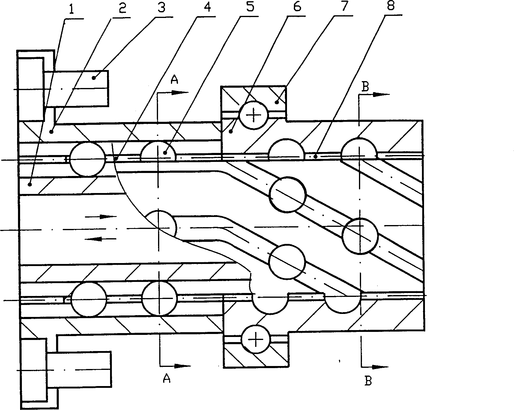
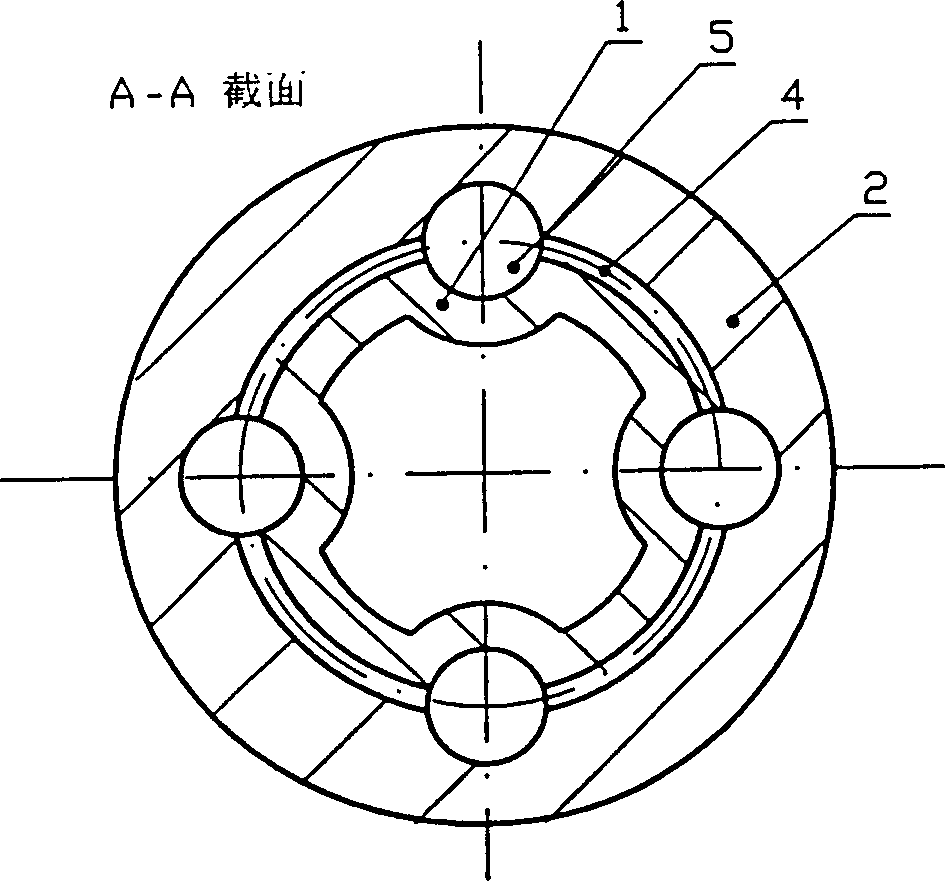
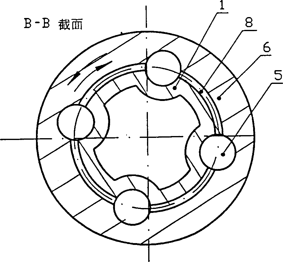
[0018] figure 1 In order to convert the linear motion into a rotary motion mechanism, it is composed of a rolling spline pair and a rolling helical pair arranged in series; the rolling spline pair is composed of an outer sleeve 2, a middle sleeve 4, an inner sleeve 1, and a steel ball 5. Its The purpose is to restrict the inner sleeve 1 to move axially; the rolling screw is composed of a spiral sleeve 6, a middle sleeve 8, an inner sleeve 1, and a steel ball 5. Its function is to drive the spiral sleeve when the inner sleeve 1 moves axially. 6 turn. Straight grooves and spiral grooves are distributed on the inner sleeve 1 . The outer sleeve 2 of the rolling spline is fastened on the cylinder block through the outer cylinder, flange and screw 3; the thrust bearing 7 restricts the helical sleeve 6 from moving axially, but can only rotate; the ...


PUM


Abstract

A roll screw engine includes screw conerting mechanism and continuous step by step rotating mechanism, of which the screw converting mechanism is formed by connecting integral key pair and roll screw pair in series arrangement. The internal sheath of above said pairs will become a complete set with its one end or two ends to be connected with one or several piston rod in series. The continuous step by step rotating mechanism includes two sets of roll screw pair with rotating direction in reverse and exporting gear wheel as two serewing sheathes to be connected with exporting gear wheel separately through clutch. The present invention uses roll screw converting mechanism in stead of crank link mechanism to convert reciprocating linear motion of piston into continuous rotating motion.

Description

(1) Technical field [0001] The invention relates to an internal combustion engine in the field of mechanical engineering, in particular to a rolling screw engine. (two), background technology [0002] The internal combustion engine is widely used in various moving machinery or transportation machinery. The current internal combustion engine mainly uses a crank connecting rod mechanism to convert the movement of the piston into rotation. This reciprocating mechanism has side pressure on the piston, and the transmission torque changes greatly. The radial thrust is very large, there is a dead point, and there are problems such as a large sliding friction loss. Therefore, the efficiency is only 0.3 to 0.4. At home and abroad, the rotary piston engine was studied in the 1950s and 1960s, but the research has been stopped because the sealing and material problems cannot be solved. Therefore, crank-connecting rod engines are still widely used so far. (3) Contents of the invention...

Claims


Application Information

Patent Timeline
Patent Type & Authority Patents(China)
IPC IPC(8): F02B75/32
Inventor 梁锡昌
Owner 梁锡昌
Why Eureka
Try Eureka