Supercharge Your Innovation With Domain-Expert AI Agents!

Non-uniformity correction method for remote sensing image

A non-uniform correction and remote sensing image technology, which is applied in image enhancement, image analysis, image data processing, etc., can solve the problems of inability to realize the calibration of the full dynamic range of the sensor, image fringes, and difficulty in achieving high-frequency on-orbit relative radiation positioning. Problems such as marking, achieving high practicability and application value, eliminating odd and even fringe noise, and requiring low accuracy

Pending Publication Date: 2022-03-25
CHANGCHUN INST OF OPTICS FINE MECHANICS & PHYSICS CHINESE ACAD OF SCI
View PDF0 Cites 1 Cited by
  • Summary
  • Abstract
  • Description
  • Claims
  • Application Information

AI Technical Summary

Problems solved by technology

[0006] Radiation calibration based on statistical methods is based on the data accumulation of massive samples imaged by each detector element of the sensor, and it is difficult to achieve high-frequency on-orbit relative radiation calibration
[0007] The application of the yaw radiation calibration method is mostly at the imaging level of the uniform field yaw calibration on the earth's surface, and the calibration of the full dynamic range of the sensor cannot be achieved.
[0008] The above relative radiometric calibration accuracy is often limited by the accuracy of the relative radiometric calibration model of the sensor and the accuracy of the radiometric calibration reference. In fact, the on-orbit imaging may deviate from the prior model and the radiometric calibration reference, resulting in images may still have non-uniformities such as streaks

Method used


Image

  • Non-uniformity correction method for remote sensing image
  • Non-uniformity correction method for remote sensing image
  • Non-uniformity correction method for remote sensing image

Examples


Embodiment Construction

[0025] The technical solutions of the present invention will be described in detail below in conjunction with the accompanying drawings and preferred embodiments.

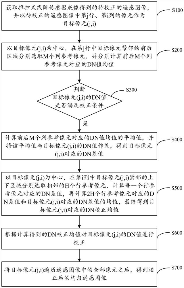
[0026] Such as figure 1 As shown, the present invention discloses a method for correcting non-uniformity of remote sensing images, the method comprising the following steps:

[0027] Step 1 (S100): Acquire the remote sensing image to be corrected obtained by the push-broom line array sensor, and use the pixel in row j and column i in the remote sensing image to be corrected as the target pixel (j,i).

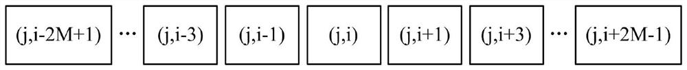
[0028] Step 2 (S200): Take the target pixel (j, i) as the center, select M columns of reference pixels in the front and rear areas immediately adjacent to the target pixel (j, i) in the jth row, and calculate the first M The mean value of the DN value corresponding to the column reference pixel and the mean value of the DN value corresponding to the last M column reference pixels, and when i is an even number, the c...


PUM


Abstract

The invention relates to a remote sensing image non-uniformity correction method, which comprises the following steps of: acquiring a to-be-corrected remote sensing image obtained by imaging of a push-broom linear array sensor, and taking pixels in the j-th row and the i-th column in the to-be-corrected remote sensing image as target pixels; judging whether the DN value of the target pixel meets a correction condition, if so, firstly calculating a DN difference value corresponding to the target pixel by utilizing the column reference pixel, and then calculating a DN correction mean value corresponding to the target pixel by taking the target pixel as a center and utilizing the row reference pixel; and correcting the DN value of the target pixel according to the calculated DN correction mean value, and finally traversing all the pixels in the remote sensing image by the target pixel to obtain a corrected uniform remote sensing image. On the basis that original feature information of the remote sensing image is reserved as much as possible, odd-even stripe noise can be effectively eliminated, the quality of the remote sensing image is improved, and high practicability and application value are achieved.

Description

technical field [0001] The invention relates to the technical field of digital image processing, in particular to a non-uniform correction method for remote sensing images. Background technique [0002] Due to the inhomogeneity of the response between the probes of the push-broom line array sensor in the space remote sensing satellite, the inconsistency of the fixed noise and dark current response, the inconsistency of the sensor electronics bias and the difference in the output circuit, the line array sensor There are certain differences in the response of each detector to the same entrance pupil radiance, which leads to the presence of stripes, s-bands and other random image noise in remote sensing images, which adversely affects the subsequent application of remote sensing images. [0003] Relative radiometric calibration is an important way to improve the radiometric quality of remote sensing satellite images. Relative radiometric calibration uses the radiometric calibr...

Claims


Application Information

Patent Timeline
IPC IPC(8): G06T5/00
CPCG06T2207/10032G06T5/80G06T5/70
Inventor 毕国玲赵宇宸周怀得赵莹付天骄刘金国
Owner CHANGCHUN INST OF OPTICS FINE MECHANICS & PHYSICS CHINESE ACAD OF SCI
Features
  • R&D
  • Intellectual Property
  • Life Sciences
  • Materials
  • Tech Scout
  • Unparalleled Data Quality
  • Higher Quality Content
  • 60% Fewer Hallucinations
Learn More