High-low voltage power distribution equipment with energy-saving performance

A power distribution equipment, energy-saving technology, applied in substation/power distribution device casing, electrical components, substation/switch layout details, etc., can solve the problem that power distribution equipment cannot effectively save energy

Pending Publication Date: 2022-03-25
深圳市承泽信息科技有限公司
View PDF1 Cites 0 Cited by
  • Summary
  • Abstract
  • Description
  • Claims
  • Application Information

AI Technical Summary

Problems solved by technology

[0005] Aiming at the deficiencies of the prior art, the present invention provides a high and low voltage energy-saving power distribution equipment, which can reduce the dust content in the power distribution equipment to prevent the increase of the resistance of the main circuit and convective heat dissipation to p

Method used


Image

  • High-low voltage power distribution equipment with energy-saving performance
  • High-low voltage power distribution equipment with energy-saving performance
  • High-low voltage power distribution equipment with energy-saving performance

Examples


Embodiment 1

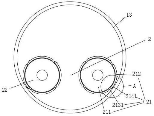
[0041] In a typical implementation, such as figure 1 , Figure 9 , Figure 11 As shown, a high and low voltage energy-saving power distribution equipment includes a housing 1, and an air inlet 11 and an air outlet 12 are opened on the housing 1, and electrostatic adsorption devices are arranged at the air inlet 11 and the air outlet 12. 2.

[0042] The outside air flows into the housing 1 through the air inlet 11 , blows to the power distribution components inside the housing 1 , and then is discharged through the air outlet 12 . When the airflow passes through the corresponding electrostatic adsorption device 2, it is purified and dust-removed by the electrostatic adsorption device 2.

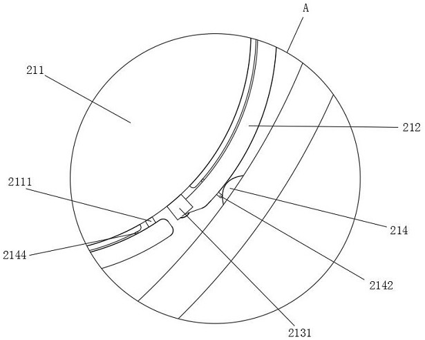
[0043] The electrostatic adsorption device 2 includes a positive pole piece 21 and a negative pole piece 22 . The positive pole piece 21 and the negative pole piece 22 are arranged opposite to each other. The air flow passes through the channel between the positive pole piece 21 and the neg...

Embodiment 2

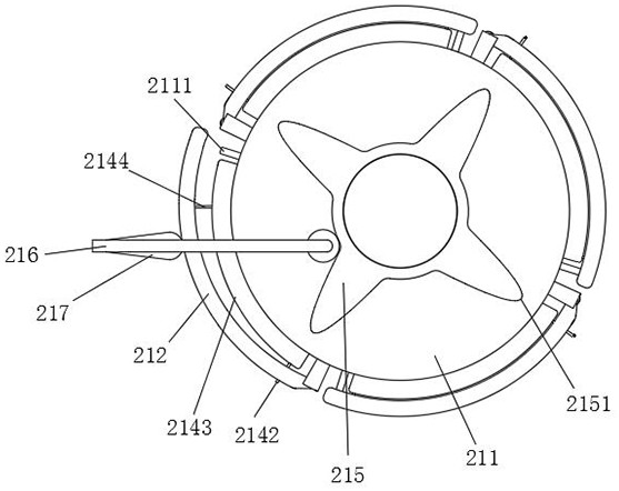
[0078] Further, such as Figure 7 , Figure 8 As shown, a roller 2161 is rolled on the moving rod 216, and the roller 2161 is offset against the transmission plate 215, so that the relative movement between the roller 2161 and the transmission plate 215 is better, and the influence of friction on the relative movement is reduced.

Embodiment 3

[0080] The difference between this embodiment and the above-mentioned embodiment is that: Figure 11 As shown, a dust removal port 14 is provided on the side wall of the processing cylinder 13, and the dust removal port 14 is opposite to the position where the dust collection plate 212 is opened. When the dust collection plate 212 is opened, the dust on the dust collection plate 212 can be removed from the Mouth 14 falls.

[0081] Further, a non-return side plate 15 is fixedly installed on the inner wall of the processing cylinder 13, and the non-return side plate 15 is opposite to the dust removal port 14, and is blocked by the non-return side plate 15 to prevent the air flow from flowing back into the processing cylinder from the dust removal port 14 13 interior.

[0082] Such as Figure 9 As shown, further, the outer wall of the processing cylinder 13 is fixedly equipped with a discharge box 16, the dust removal block 217, the second elastic member 218, and the guide fram...


PUM


Abstract

The invention relates to the technical field of energy conservation of power distribution equipment, and discloses high-low voltage power distribution equipment with energy conservation. Comprising a shell, an air inlet is formed in one side of the shell, and an air outlet is formed in the other side of the shell; electrostatic adsorption devices are arranged in the air inlet and the air outlet; and positive pole pieces of the electrostatic adsorption devices comprise positive pole rings, dust collection plates, triggering devices, first elastic pieces and dust removal blocks. Dust is adsorbed through dust collection plates in electrostatic adsorption devices in an air inlet and an air outlet, and when the positive electrode ring rotates to drive the dust collection plates to move to be triggered by a triggering device, the other ends of the dust collection plates are separated from the positive electrode ring, so that the dust collection plates are opened; and meanwhile, the positive electrode ring rotates to drive the dust removal block to reciprocate, so that the dust collection plate is in contact with the dust removal block to impact dust adsorbed on the dust collection plate when the dust collection plate is opened to the maximum position, the dust is isolated outside the power distribution equipment, and the dust is prevented from entering the power distribution equipment from the outside to influence the work of power distribution elements.

Description

technical field [0001] The invention relates to the technical field of power distribution equipment energy saving, in particular to high and low voltage power distribution equipment with energy saving properties. Background technique [0002] Power distribution equipment is a general term for high-voltage distribution cabinets, generators, transformers, power lines, circuit breakers, low-voltage switchgear, switchboards, switch boxes, control boxes and other equipment in the power system. Among them, the power distribution cabinet is affected by its characteristics, and most of the power distribution cabinets are installed in an independent and relatively closed space to ensure the safe use of the power distribution cabinet. The power distribution cabinet is used to integrate and control the use of the circuit, but due to the use environment of the power distribution cabinet and its own use, the circuit will generate power loss after passing through the power distribution ca...

Claims


Application Information

Patent Timeline
IPC IPC(8): H02B1/56H02B1/28H02B1/26B01D45/08
CPCH02B1/565H02B1/28H02B1/26B01D45/08
Inventor 张仁政
Owner 深圳市承泽信息科技有限公司
Why Eureka
Try Eureka