

High-gain zero-ripple passive clamping type Boost converter and control method thereof
Patent Information
- Authority / Receiving Office
- CN · China
- Patent Type
- Applications(China)
- Current Assignee / Owner
- ANHUI UNIVERSITY OF TECHNOLOGY
- Publication Date
- 2022-03-25
- Estimated Expiration
- Not applicable · inactive patent
Smart Images
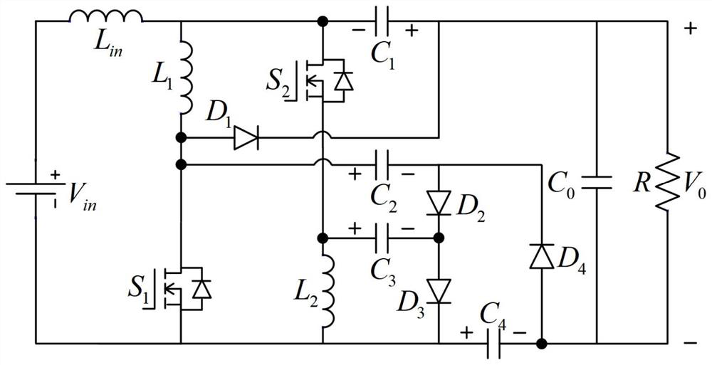
Figure 1 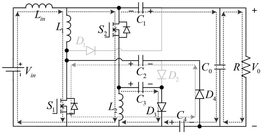
Figure 2 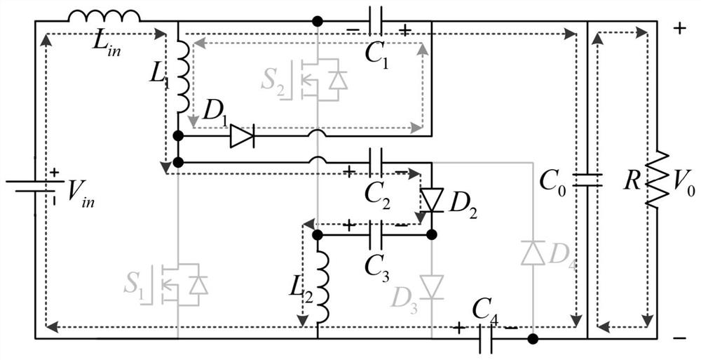
Figure 3
Abstract
Description
technical field
[0001] The invention relates to the technical field of power electronic converters, in particular to a high-gain zero-ripple passive clamping boost converter and a control method thereof. Background technique
[0002] As global energy and environmental issues continue to emerge, new energy power generation technologies represented by photovoltaics and fuel cells have attracted widespread attention due to their high efficiency, pollution-free, renewable and non-regional restrictions. However, in new energy power generation systems, the output voltage of photovoltaic panels and fuel cells is relatively low, generally around 20V-50V, which cannot directly provide power to the grid or local loads. In order to adapt the energy captured by fuel cells and solar photovoltaic panels to grid-connected power generation or supply power to local loads, a high-gain DC-DC converter is required to boost its lower output voltage to a higher DC voltage above 200V, Then throug...