
Neutral-point voltage balance control system and method based on power factor angle

A technology of power factor angle and voltage balance, applied in the direction of output power conversion device, AC power input conversion to DC power output, electrical components, etc., can solve the problems of long adjustment period and low adjustment accuracy, and achieve good real-time performance, The control method is simple and the effect of improving the quality of the output waveform

Inactive Publication Date: 2014-09-17
NANJING UNIV OF SCI & TECH
View PDF3 Cites 10 Cited by
  • Summary
  • Abstract
  • Description
  • Claims
  • Application Information

AI Technical Summary

Problems solved by technology

For example: Literature 1 (Gong Bo, Cheng Shanmei, Qin Yi. Carrier-based three-level neutral point voltage balance control strategy [J]. Journal of Electrotechnical Society, 2013,28(6):172-177.) and patent 1( Cheng Shanmei, Gong Bo, Ning Bowen, Liu Jiang. A mid-point voltage control method for NPC type three-level inverter based on carrier amplitude shift: China, CN201210140269.0.2012-09-19.) A carrier-based The variable-amplitude SPWM control scheme realizes midpoint voltage balance by sampling the midpoint voltage and changing the carrier amplitude in real time. The low-frequency pulsation has no control effect, and the adjustment period is long and the adjustment accuracy is not high

Method used


Image

  • Neutral-point voltage balance control system and method based on power factor angle
  • Neutral-point voltage balance control system and method based on power factor angle
  • Neutral-point voltage balance control system and method based on power factor angle

Examples


Embodiment 1

[0092] In order to verify the feasibility and effectiveness of a midpoint voltage balance control method based on the power factor angle proposed by the present invention, a three-level inverter circuit under the control of the SPWM method was built using the Simulink tool in MATLAB. The electrical parameter settings in the simulation process are as follows:

[0093]

[0094] Image 6 The simulation running waveforms under different values ​​of k are given. Before 0.4s, the traditional SPWM modulation method is adopted, and the peak-to-peak value of the upper and lower capacitor voltage difference changes is about 10V. At 0.4s, it is switched to the midpoint voltage balance control method based on the power factor angle proposed by the present invention. When k takes different values, the pulsating amplitude of the variation of the voltage difference between the upper and lower capacitors is as follows: Image 6 As shown in (a) to (c), it can be seen from the figure that ...


PUM


Abstract

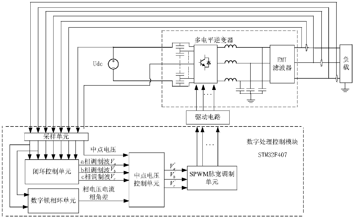
The invention discloses a neutral-point voltage balance control system and method based on a power factor angle. The system comprises a multi-level inverter and a digital processing control module. The digital processing control module comprises a sampling unit, a closed-loop control unit, a digital phase-locked loop unit, a neutral-point voltage control unit and an SPWM pulse width modulation unit. The sampling unit collects direct-current bus voltage signals of the multi-level inverter, direct-current bus neutral-point voltage signals of the multi-level inverter, and three-phase voltage and three-phase current signals output by the multi-level inverter, the signals are processed through the closed-loop control unit to obtain three-phase modulating waves, the three-phase modulating waves are calculated through the digital phase-locked loop unit to obtain the power factor angle, the three-phase modulating waves, the power factor angle and the direct-current bus neutral-point voltage signals are processed through the neutral-point voltage control unit to obtain new three-phase modulating waves, the new three-phase modulating waves are processed through the SPWM pulse width modulation unit to obtain the pulse width modulation control signals, and the signals control the working state of each switching tube of the multi-level inverter through a drive circuit. According to the method, the low-frequency pulse amplitude of neutral-point voltage can be lowered, and neutral-point voltage balance can be achieved.

Description

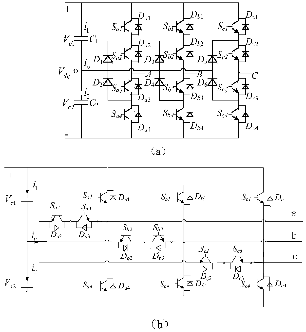
technical field [0001] The invention belongs to the field of control technology in power electronic conversion technology, in particular to a midpoint voltage balance control system and method based on power factor angle. Background technique [0002] In recent years, multilevel inverters have been widely used in high-voltage, medium-to-high-power conversion occasions; their circuit topology and control methods have become a research hotspot today. Compared with the two-level inverter, the multi-level inverter has more output levels, and the obtained ladder wave platform has more orders, so the closer to the standard sine wave, the less its harmonic components. [0003] The topology of multilevel inverters can be roughly divided into three categories: diode-clamped, cascaded, and flying-capacitor-type, of which the most widely used is the diode-clamped inverter. Taking the three-level inverter as an example, the three-level diode-clamped inverter can be divided into a neutr...

Claims


Application Information

Patent Timeline
IPC IPC(8): H02M7/483H02M7/5387
Inventor 吕建国胡文斌吴馥云哈进兵姚凯吴军基
Owner NANJING UNIV OF SCI & TECH
Learn More