
Midpoint voltage balance control system and method with low frequency oscillation suppression function

A low-frequency oscillation, voltage balance technology, applied in the output power conversion device, electrical components, AC power input into DC power output and other directions, can solve the problem of no midpoint voltage balance adjustment, no midpoint voltage balance control, Affect the output current harmonic characteristics and other problems, to achieve the effect of eliminating low-frequency oscillation, good real-time performance, and improving the quality of the output waveform

Inactive Publication Date: 2016-09-21
NANJING UNIV OF SCI & TECH
View PDF5 Cites 1 Cited by
  • Summary
  • Abstract
  • Description
  • Claims
  • Application Information

AI Technical Summary

Problems solved by technology

For example: Literature 1 (Wang Xinyu, He Yingjie, Liu Jinjun. The control mechanism of mid-point voltage balance on the DC side of three-level inverters injected into zero-sequence component SPWM modulation[J]. Journal of Electrotechnical Society, 2011,26(5):71- 77.) The mid-point voltage control is realized by injecting 6 times the zero-sequence component into the three-phase modulation wave control command voltage, but this method is relatively complicated, and it is controlled based on a power frequency cycle, which is similar to the method based on the switching cycle. ratio, the adjustment time is too long; Document 2 (Song Wenxiang, Chen Guocheng, etc. A three-level space vector modulation method with midpoint potential balance function and its realization [J]. Chinese Electrical Engineering, 2006, 26 (12 ):96-100.) On the basis of the traditional seven-segment SVPWM control method that does not have the function of midpoint voltage balance adjustment, a new SVPWM that combines thirteen-segment, nine-segment, and seven-segment hybrid modulation is proposed The control method controls the midpoint voltage. It selects the modulation mode in intervals within a power frequency cycle. In the thirteen-segment modulation mode, the switching tube operates 12 times in each switching cycle, and in the nine-segment modulation mode, each switch The periodic switching tube operates 8 times, so the average switching loss of this hybrid modulation method is greatly increased compared with the traditional seven-segment SVPWM control method
Document 3 (Cheng Shanmei, Wang Dan, Xia Litao, Wan Shuyun. Research on Discontinuous Space Vector Pulse Width Modulation [J], Servo Technology, 2002,36(4):37-40.) mainly studies several discontinuous The space vector pulse width modulation strategy is aimed at a certain phase in a certain area within the power frequency cycle, thereby reducing switching losses, but this control method does not have the ability to control the midpoint voltage balance
[0005] To sum up, the traditional SVPWM, DPWMx, and SPWM control methods generally do not have the ability to adjust the midpoint voltage balance, and the traditional DPWMx method keeps a certain phase of the switch in a continuous interval within the power frequency cycle, so it can reduce Switching loss, but in the non-action area of ​​the switch, the ripple of the inverter output inductor current increases, the longer the time in the non-action area, the larger the ripple, which will inevitably affect the harmonic characteristics of the output current

Method used


Image

  • Midpoint voltage balance control system and method with low frequency oscillation suppression function
  • Midpoint voltage balance control system and method with low frequency oscillation suppression function
  • Midpoint voltage balance control system and method with low frequency oscillation suppression function

Examples


Embodiment 1

[0084] For verifying that the present invention proposes the feasibility and effectiveness of a kind of midpoint voltage balance control method with low-frequency oscillation suppression function, utilize the Simulink tool in MATLAB to build up the three-level inverter circuit under the control of SPWM method respectively, the present invention's Three-level inverter circuit under the control of DPWM method. The electrical parameter settings in the simulation process are as follows in Table 3:

[0085] Table 3 Electrical parameter settings during simulation

[0086]

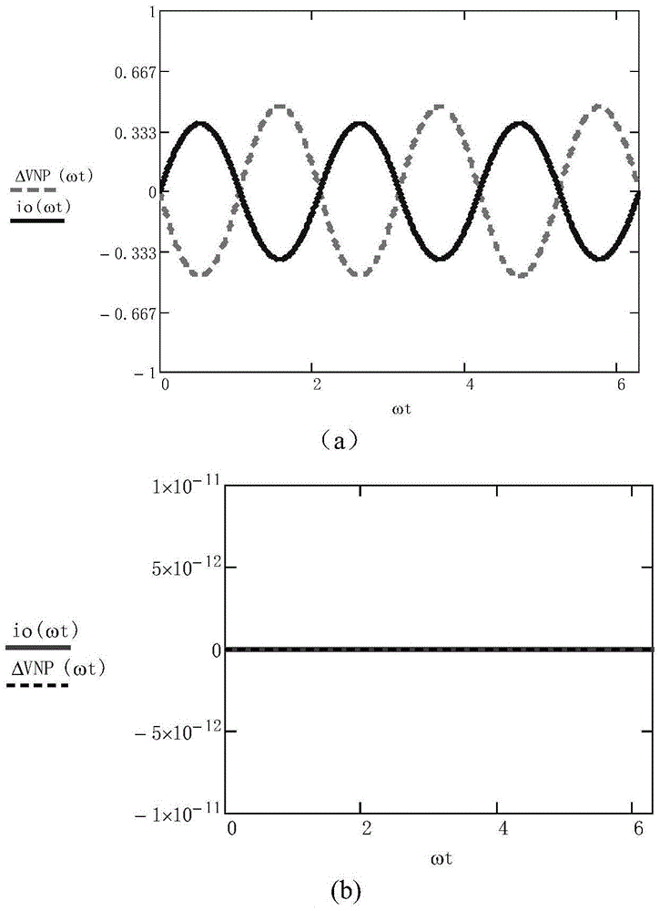
[0087] Image 6 is the DC bus capacitor C under the control of the two methods 1 、C 2 The voltage V c1 , V c2 simulated waveform. Image 6 (a) is the simulation waveform of the DC bus capacitor voltage under the traditional SPWM method, and the DC bus capacitor C 1 、C 2 The voltage V c1 , V c2 Oscillating at three times the fundamental frequency is consistent with the above theoretical analysis; Im...


PUM


Abstract

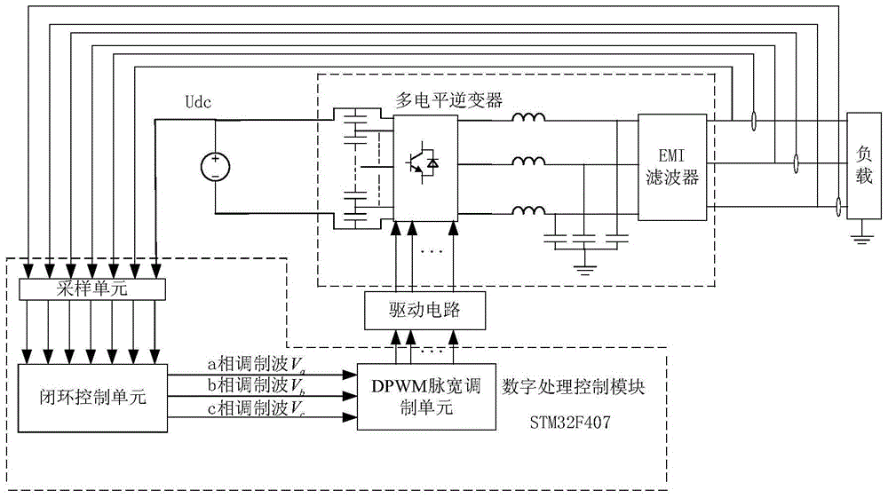
The invention discloses a mid-point voltage balance control system and method with low-frequency oscillation suppression function. The system includes a multilevel inverter and a digital processing control module, wherein the digital processing control module includes a sequentially connected sampling unit, a closed-loop control unit and a DPWM pulse width modulation unit; the output of the DPWM pulse width modulation unit is driven by The circuit is connected to each switching tube of each phase bridge arm of the multi-level inverter. The method is as follows: in each switching period, the sampling unit separately collects the DC bus voltage signal of the multi-level inverter, the three-phase voltage signal and the three-phase current signal output by the multi-level inverter; the collected signals are passed through The closed-loop control unit processes the three-phase modulation wave; the three-phase modulation wave is processed by the DPWM pulse width modulation unit to obtain the pulse width modulation control signal, and the signal controls the working state of each phase switch tube of the multi-level inverter through the drive circuit. The invention can suppress the low-frequency oscillation of the midpoint voltage of the DC bus bar of the multilevel inverter and realize the midpoint voltage balance.

Description

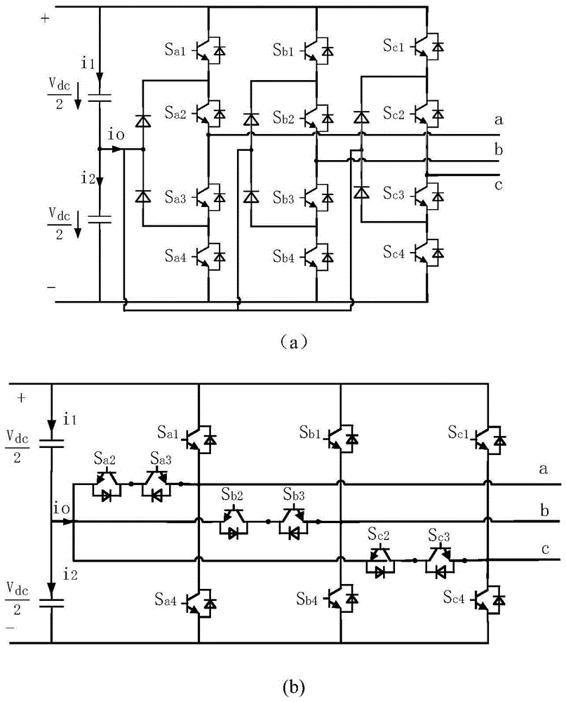
technical field [0001] The invention belongs to the field of control technology in power electronic conversion technology, in particular to a mid-point voltage balance control system and method with low-frequency oscillation suppression function. Background technique [0002] In recent years, multilevel inverters have been widely used in high-voltage, medium-to-high-power conversion occasions; their circuit topology and control methods have become a research hotspot today. Compared with the two-level inverter, the multi-level inverter has many advantages such as low voltage stress of the switching tube, low electromagnetic noise, and low harmonic distortion rate of the output voltage. [0003] The topology of multilevel inverters can be roughly divided into three categories: diode-clamped, cascaded, and flying-capacitor-type, of which the most widely used is the diode-clamped inverter. Taking the three-level inverter as an example, the three-level diode-clamped inverter can...

Claims


Application Information

Patent Timeline
Patent Type & Authority Patents(China)
IPC IPC(8): H02M7/487H02M1/12
CPCH02M7/4833
Inventor 吕建国胡文斌吴馥云陆晓玉戴双飞文晞畅吴军基
Owner NANJING UNIV OF SCI & TECH
Learn More