Control method and control system for inhibiting low-frequency oscillation of magnetic bearing system

A magnetic bearing and low-frequency oscillation technology, applied in the direction of electrical program control, sequence/logic controller program control, etc., can solve the problems of sensor lead-out line and magnetic bearing power line length, system oscillation, etc.

Active Publication Date: 2012-12-19
TSINGHUA UNIV
View PDF4 Cites 0 Cited by
  • Summary
  • Abstract
  • Description
  • Claims
  • Application Information

AI Technical Summary

Problems solved by technology

In addition, the sensor lead-out lines and magnetic bearing power lines of large-scale magnetic bearing systems are usually long, and when the electromagnetic compatibility design is unreasonable, some specific frequency interference signals may be fed in, and system oscillation may also be caused

Method used


Image

  • Control method and control system for inhibiting low-frequency oscillation of magnetic bearing system
  • Control method and control system for inhibiting low-frequency oscillation of magnetic bearing system
  • Control method and control system for inhibiting low-frequency oscillation of magnetic bearing system

Examples


Embodiment 1

[0050]The present invention also provides a magnetic bearing system, which includes a frame, a rotor, a prime mover and its driver, a magnetic bearing, a rotor displacement sensor, a power amplifier, a monitoring computer, and a control computer. The rotor displacement sensor is arranged on the frame, The output end of the rotor displacement sensor is electrically connected to the control computer, and is also connected to the monitoring computer. The command output of the control computer is electrically connected to the power amplifier. The magnetic bearing is arranged on the frame, and the input end of the magnetic bearing It is electrically connected to the power amplifier, and the rotor is fixedly connected to the prime mover or mechanically connected through a coupling. In addition to being connected to the prime mover, the rotor has no mechanical contact with other parts in the system in the working state, and a certain gap is maintained. The preset in the control compute...

Embodiment 2

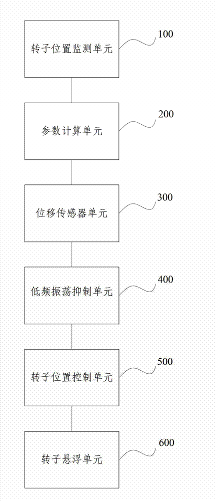
[0070] The present invention provides a magnetic bearing control system, which includes a rotor, and further includes:

[0071] A rotor position monitoring unit (100), used to record the rotor position oscillation waveform, and calculate the oscillation frequency f according to the oscillation waveform O ;

[0072] A parameter calculation unit (200), for setting the sampling period T S , phase compensation band half-band width f B , according to the system oscillation frequency f O , sampling period T S and the half-bandwidth of the phase compensation band f B Calculating the parameters of the low-frequency oscillation suppression unit;

[0073] A displacement sensor unit (300), used to collect the displacement value of the rotor;

[0074] A low-frequency oscillation suppression unit (400), configured to calculate a signal after low-frequency suppression according to the displacement value and the parameters of the low-frequency oscillation suppression unit;

[0075] A ...

Embodiment 3

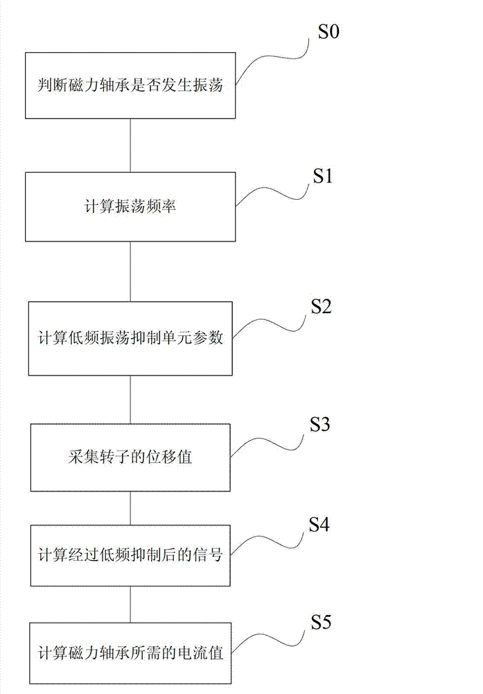
[0080] The present invention also provides a magnetic bearing control method, which includes the following steps:

[0081] S1. Record the rotor position oscillation waveform, and calculate the oscillation frequency f according to the oscillation waveform O ;

[0082] S2. Set the sampling period T S , phase compensation band half-band width f B , according to the system oscillation frequency f O , sampling period T S and the half-bandwidth of the phase compensation band f B Calculating the parameters of the low-frequency oscillation suppression unit;

[0083] S3. collecting the displacement value of the rotor;

[0084] S4. Calculate the signal after low-frequency suppression according to the displacement value and the low-frequency oscillation suppression unit parameters;

[0085] S5. Calculate the current value required by the magnetic bearing according to the signal after the low-frequency suppression;

[0086] S6. Suspending the rotor according to the current value. ...


PUM


Abstract

The invention provides a control method and a control system for a magnetic bearing system. The control system comprises a rotor position monitoring unit used for recording an oscillation wave form on a position of a rotor, and figuring up an oscillation frequency fO according to the oscillation wave form, a parameter computing unit used for setting a sampling period TS, a phase compensation frequency band half frequency width fB, and figuring up parameters of a low-frequency oscillation inhibition unit according to the oscillation frequency fO, the sampling period TS and the phase compensation frequency band half frequency width fB, a displacement sensor component used for collecting a displacement value of the rotor, the low-frequency oscillation inhibition unit used for figuring up a signal subjected to low-frequency inhibition according to the displacement value and the parameters of the low-frequency oscillation inhibition unit, a rotor position control unit used for figuring up a current value for the magnetic bearing according to the signal subjected to low-frequency inhibition, and a rotor suspension unit used for suspending the rotor according to the current value. According to the invention, a controller is subjected to phase compensation, and the possible low-frequency oscillation in the magnetic bearing is eliminated.

Description

technical field [0001] The invention relates to the technical field of control of a bearing system, in particular to a control method and system for suppressing low-frequency oscillation of a magnetic bearing system. Background technique [0002] The magnetic bearing system is a frictionless and non-lubricating bearing system, which is suitable for some rotating machines with special requirements. At present, the application of magnetic bearings has become increasingly widespread. When the magnetic bearing system is working, the rotor is kept in a suspended state by the electromagnetic force and has no contact with the stator assembly. The magnetic bearing itself is unstable, so it is necessary to adjust the electromagnetic force according to the position of the rotor in real time to ensure that the rotor is suspended in the working position stably. The adjustment of the electromagnetic force of the magnetic bearing is realized by adjusting the bearing current. [0003] Co...

Claims


Application Information

Patent Timeline
Patent Type & Authority Applications(China)
IPC IPC(8): G05B19/04
Inventor 孙喆周燕时振刚石磊于溯源
Owner TSINGHUA UNIV
Why Eureka
Try Eureka