
Surface acoustic wave resonator and filter

A surface acoustic wave and resonator technology, applied to electrical components, impedance networks, etc., to achieve the effects of improving Q value and stability, reducing device loss, and improving stability

Pending Publication Date: 2022-03-25
MAXSCEND MICROELECTRONICS CO LTD
View PDF8 Cites 0 Cited by
  • Summary
  • Abstract
  • Description
  • Claims
  • Application Information

AI Technical Summary

Problems solved by technology

[0003] At present, the operating frequency of surface acoustic wave devices is generally below 3GHz. Even if the super high performance (Incredible High Performance, IHP) surface acoustic wave structure is used, the frequency can reach up to about 3.5GHz, and it cannot be used at higher frequencies (such as 5GHz). Work

Method used


Image

  • Surface acoustic wave resonator and filter
  • Surface acoustic wave resonator and filter
  • Surface acoustic wave resonator and filter

Examples


Embodiment Construction

[0025] The present invention will be further described in detail below in conjunction with the accompanying drawings and embodiments. It should be understood that the specific embodiments described here are only used to explain the present invention, but not to limit the present invention. In addition, it should be noted that, for the convenience of description, only some structures related to the present invention are shown in the drawings but not all structures.

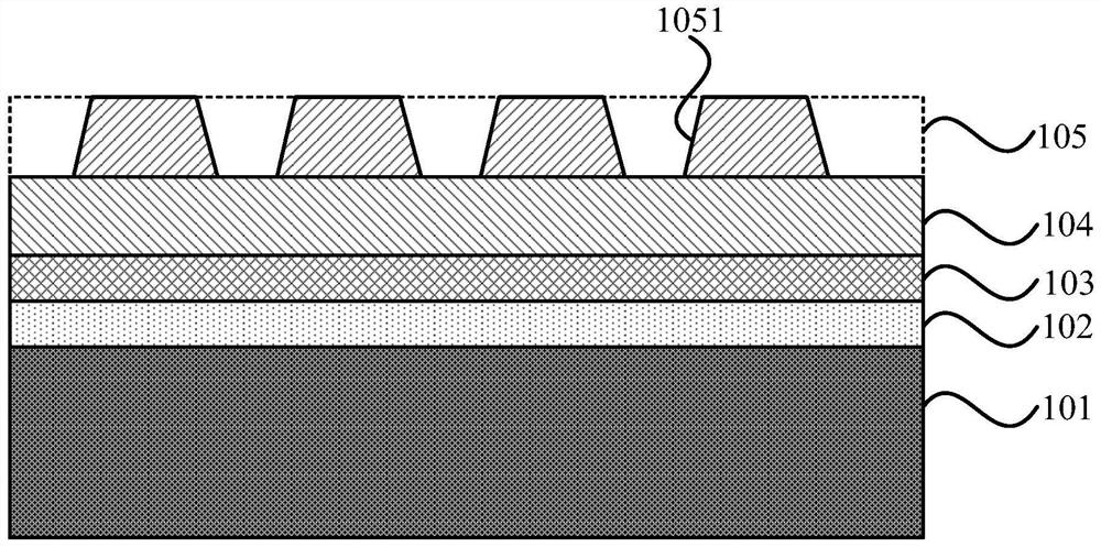
[0026] figure 1 It is a schematic structural diagram of a surface acoustic wave resonator provided by the embodiment of the present invention. The embodiment of the present invention can be applied to the production of high-frequency and large-bandwidth (5GHz) surface acoustic wave devices. Refer to figure 1 , the surface acoustic wave resonator includes: a support layer 101, an energy trap layer 102, a temperature compensation layer 103, a piezoelectric layer 104, and an interdigital transducer layer 105 that are...


PUM

PropertyMeasurementUnit
Thicknessaaaaaaaaaa
Thicknessaaaaaaaaaa

Abstract

The embodiment of the invention discloses a surface acoustic wave resonator and a filter. The resonator comprises a supporting layer, an energy trap layer, a temperature compensation layer, a piezoelectric layer and an interdigital transducer layer which are sequentially stacked, the interdigital transducer layer comprises a plurality of interdigital transducers, the material of the piezoelectric layer comprises X-40Y lithium niobate, the acoustic bulk wave propagation velocity of the support layer is greater than the acoustic surface wave propagation velocity of the piezoelectric layer, and the energy trap layer is used for capturing parasitic charges on the surface of the support layer to improve the Q value of the acoustic surface wave resonator. According to the embodiment of the invention, the piezoelectric layer and the supporting layer of the resonator are improved, and the speed of transmitting sound waves by X-40Y lithium niobate is relatively high, so that the working frequency of the resonator is greatly improved and reaches 5G and more than 5G; the acoustic bulk wave propagation speed of the supporting layer is greater than that of the surface acoustic wave propagation speed of the piezoelectric layer, energy is limited on the surface, and bulk wave leakage is avoided, so that the device loss is reduced; the energy trap layer can improve the Q value to enhance the stability of the surface acoustic wave resonator.

Description

technical field [0001] Embodiments of the present invention relate to the technical field of surface acoustic waves, and in particular, to a surface acoustic wave resonator and filter. Background technique [0002] With the development of communication technology from 2G to 5G, the number of communication frequency bands has gradually increased (from 4 frequency bands in 2G to more than 50 frequency bands in 5G). In order to improve the compatibility of smartphones with different communication systems, the amount of filters required by 5G smartphones will increase significantly, driving the large-scale growth of the filter market. At present, the radio frequency filter widely used in wireless communication terminals is the surface acoustic wave filter, which is responsible for receiving and transmitting the radio frequency signal of the channel, and outputs the signal of a specific frequency among the various input radio frequency signals. Due to the advent of 5G communicat...

Claims


Application Information

Patent Timeline
IPC IPC(8): H03H9/02H03H9/64
CPCH03H9/02543H03H9/02661H03H9/02834H03H9/64
Inventor 宋崇希王放
Owner MAXSCEND MICROELECTRONICS CO LTD
Learn More