
Runner structure for chip cooling and manufacturing method thereof

A flow channel and chip technology, which is applied in the field of chip cooling flow channel structure and its production, can solve the problem of low heat dissipation capacity of the micro channel structure, and achieve the effects of low cost, improved heat dissipation capacity, and improved heat dissipation performance

Active Publication Date: 2022-03-25
NAT CENT FOR ADVANCED PACKAGING +1
View PDF10 Cites 1 Cited by
  • Summary
  • Abstract
  • Description
  • Claims
  • Application Information

AI Technical Summary

Problems solved by technology

[0003] The purpose of the present invention is to provide a flow channel structure for chip cooling and a manufacturing method thereof, so as to solve the problem that the heat dissipation capacity of the existing micro-channel structure is not high

Method used


Image

  • Runner structure for chip cooling and manufacturing method thereof
  • Runner structure for chip cooling and manufacturing method thereof
  • Runner structure for chip cooling and manufacturing method thereof

Examples


Embodiment Construction

[0026] The present invention will be further described below in conjunction with specific embodiments with reference to the accompanying drawings.

[0027] It should be noted that components in the various figures may be shown exaggerated for the purpose of illustration and are not necessarily true to scale. In the various figures, identical or functionally identical components are assigned the same reference symbols.

[0028] In the present invention, unless otherwise specified, "arranged on", "arranged on" and "arranged on" do not exclude the presence of intermediates between the two. In addition, "arranged on or above" only means the relative positional relationship between two parts, and under certain circumstances, such as after the product direction is reversed, it can also be converted to "arranged under or below", and vice versa Of course.

[0029] In the present invention, each embodiment is only intended to illustrate the solutions of the present invention, and sho...


PUM


Abstract

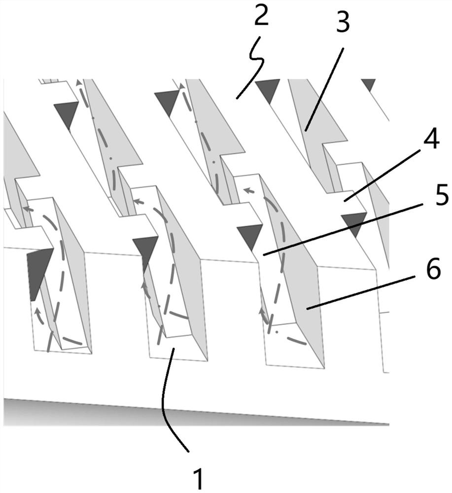
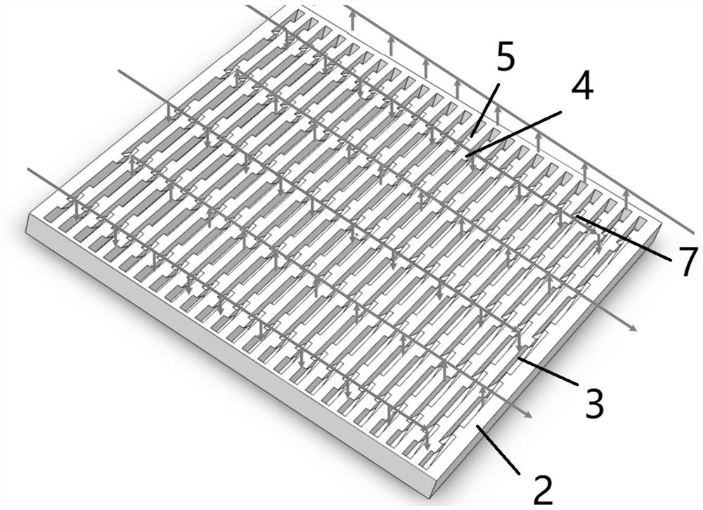
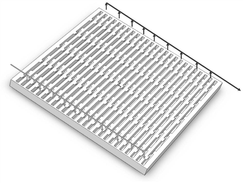
The invention provides a flow channel structure for chip cooling and a manufacturing method thereof, and the structure comprises at least one first fin which is disposed on a first side wall surface of a flow channel and extends along a first direction so as to guide a cooling liquid in the flow channel along the first direction; the first fins are arranged on the first side wall face of the flow channel, the second fins are arranged on the second side wall face of the flow channel, the second fins extend in the second direction so as to be used for guiding cooling liquid in the flow channel in the second direction, and the first fins and the second fins intersect with each other and communicate with each other at the intersection.

Description

technical field [0001] The invention relates to the technical field of integrated circuits, in particular to a flow channel structure for chip cooling and a manufacturing method thereof. Background technique [0002] With the evolution of semiconductor process nodes, the number of transistors per unit area is increasing, the functions and computing capabilities of chips are becoming stronger, and the power density and heat generation are also increasing; at the same time, with the development of system-in-package technology , the integration level is getting higher and higher, and higher requirements are put forward for the lightness, thinness, and miniaturization of packaged products, and the power consumption per unit area is also increasing, which makes the problem of heat dissipation more prominent. Based on the heat dissipation structure of micro-channels, micro-channels with a cross-sectional shape of only tens to hundreds of microns are fabricated by photolithography,...

Claims


Application Information

Patent Timeline
Patent Type & Authority Applications(China)
IPC IPC(8): H05K3/00H05K1/02H01L23/473
CPCH05K1/0201H05K3/00H01L23/473
Inventor 陈钏周云燕陈海英曹立强
Owner NAT CENT FOR ADVANCED PACKAGING
Learn More