
Method and device for dynamically adjusting X-ray collimator of medical CT (Computed Tomography) machine

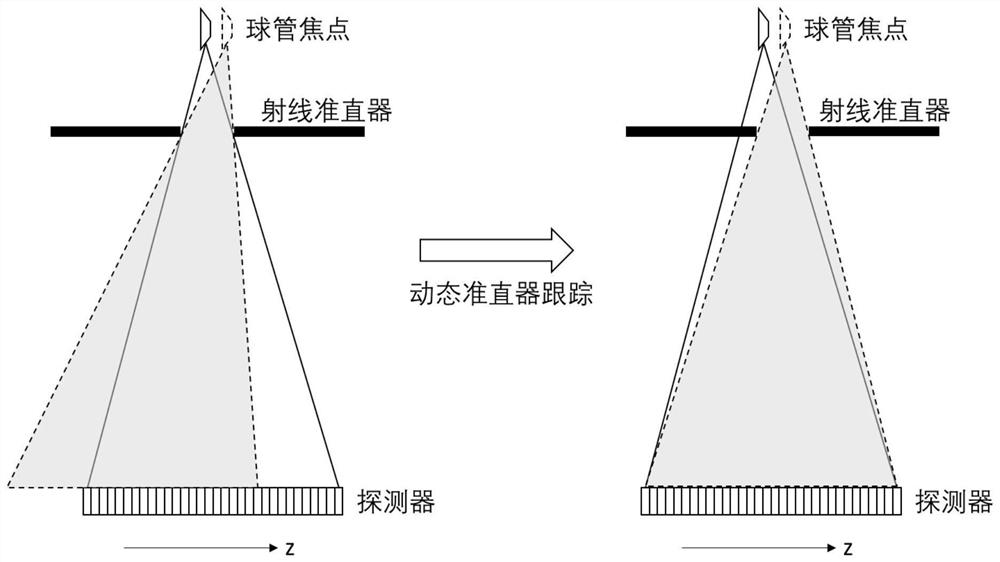
A dynamic adjustment and collimator technology, applied in the fields of radiological diagnosis instruments, applications, medical science, etc., can solve the problems of compensation lag, affecting the continuity of scanning control timing, and ineffectiveness, and achieve a coherent scanning process. Effect

Pending Publication Date: 2022-03-29
NANJING ANKE MEDICAL TECH CO LTD
View PDF0 Cites 0 Cited by
  • Summary
  • Abstract
  • Description
  • Claims
  • Application Information

AI Technical Summary

Problems solved by technology

[0003] This collimator positioning technology has obvious shortcomings. First, the compensation in this way is lagging and not real-time. It can only be used for the next scan, but not for the previous scan. Secondly, the actual scan control timing needs to wait. The current scan can only be performed after the compensation is completed. This method of compensation requires additional time, so it will affect the continuity of the scan control sequence, especially when the conditions of the two scans before and after are unchanged, only the focus of the tube needs to be compensated. ;Finally, it is also the biggest problem. The offset of the actual tube focus is not fixed. The offset of the tube focus depends on factors such as the rack speed, the tube anode speed, the heat capacity of the tube, kV, mA, etc. If the tube The offset of the focus has changed before and after compensation, and this method cannot be used for effective compensation

Method used


Image

  • Method and device for dynamically adjusting X-ray collimator of medical CT (Computed Tomography) machine
  • Method and device for dynamically adjusting X-ray collimator of medical CT (Computed Tomography) machine
  • Method and device for dynamically adjusting X-ray collimator of medical CT (Computed Tomography) machine

Examples


Embodiment 1

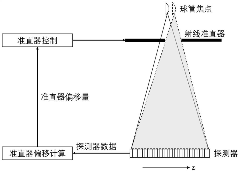
[0054] This embodiment provides a method for dynamically adjusting the X-ray collimator of a medical CT machine. The detector of the CT machine includes a plurality of detector modules arranged in the x direction, and each detector module includes multiple rows of detectors in the z direction. unit.

[0055] 1. The dynamic adjustment method of the collimator specifically includes steps:

[0056] Continuously monitor the exposure start signal of the X-ray tube;

[0057] Before the exposure starts, obtain the background data corresponding to the detector unit of a detector module, and calculate the average value of the background data corresponding to the detector unit; data;

[0058] After the exposure starts, the collimator control strategy is executed more than once to adjust the position of the collimator, and the interval between two adjacent adjustments is preset, until the exposure stops, and the adjustment is completed;

[0059] Wherein, the steps of executing the col...

Embodiment 2

[0081] 1. The collimator control strategy in this embodiment is implemented on the basis of the above-mentioned PID algorithm.

[0082] Such as Figure 4 shown, including the following steps:

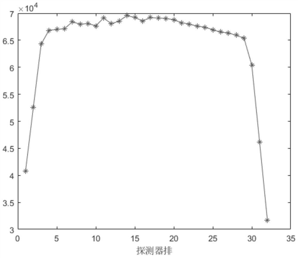
[0083] (1) Before the exposure starts, the background data of the current kth row and the penultimate kth row are taken in a loop to calculate their average value B k , B N-k+1 , and monitor the exposure start signal;

[0084] (2) After the exposure starts, stop taking background data, set a FIFO buffer with a length of L, and clear it;

[0085] (3) Take the exposure data of the current kth row and the penultimate kth row and calculate their average value A k 、A N-k+1 ;

[0086] (4) Calculate the difference value

[0087]

[0088] (5) put current δ into FIFO cache, and calculate the average value of all values ​​in the cache: 1;

[0089] (6) Calculate the rate of change of the current δ: D=δ 1 -δ 2 ;

[0090] (7) Let P=δ, calculate the offset of the collimator center as: ...

Embodiment 3

[0115] A dynamic adjustment device for an X-ray collimator of a medical CT machine, characterized in that it comprises:

[0116] The exposure signal monitoring module is used to continuously monitor the exposure start signal of the X-ray tube;

[0117] The background data acquisition module is used to obtain the background data corresponding to the detector unit of a detector module, and calculate the background data average value corresponding to the detector unit;

[0118] The control module is used to execute the collimator control strategy more than once after the exposure starts, adjust the position of the collimator, set the interval between two adjacent adjustments, and issue an instruction to end the adjustment when the exposure stops;

[0119] The exposure data acquisition module acquires the exposure data received by the k-th row of detector units and the penultimate k-th row of detector units of the selected detector module, and calculates the corresponding average ...


PUM


Abstract

The invention relates to the technical field of CT image calibration, and discloses a method and device for dynamically adjusting an X-ray collimator of a medical CT machine, and the method comprises the steps: continuously monitoring an exposure starting signal of an X-ray bulb tube; before exposure is started, background data corresponding to a detector unit of a detector module is obtained; and after exposure is started, executing more than one collimator control strategy, calculating the offset of the center of the collimator according to all difference values obtained by executing the collimator control strategy every time, adjusting the position of the collimator, and ending the adjustment at the interval of a preset time between two adjacent adjustments until the exposure is stopped. The position of the collimator can be adjusted in real time, the adjusted collimator acts on current scanning, more accurate scanning data is obtained, the scanning process is more coherent, and the method can adapt to different scanning conditions.

Description

technical field [0001] The invention relates to the technical field of medical CT image calibration, in particular to a dynamic tracking adjustment method for an X-ray collimator of a medical CT machine. Background technique [0002] During the use of CT, due to scanning conditions and other factors, the position of the focus of the X-ray tube in the z direction is not fixed, and there is an offset, and because the X-ray collimator is very close to the position of the tube, the Offset will cause large changes in the shadow of the collimator on the detector. Variations in shading can further inaccurate the calibration data, causing artifacts to appear on the image. At present, the conventional solution to this problem is to use the collimator positioning technology, which is to scan first and then adjust the collimator to compensate, that is, to calculate the offset of the tube focus by performing complex calibration on the previous scan data, and then adjust the collimator....

Claims


Application Information

Patent Timeline
IPC IPC(8): A61B6/00A61B6/03
CPCA61B6/4021A61B6/4035A61B6/52A61B6/032
Inventor 蔡小敏徐丹
Owner NANJING ANKE MEDICAL TECH CO LTD
Learn More