Drainage device for liquid in pulling-out tubular column, tubular column pulling-out structure and tubular column pulling-out method

A technology for pipe strings and cylinders, which is applied in the field of liquid drainage devices in pipe strings, and can solve problems such as operator pollution, equipment pollution, and oil not falling to the ground.

Pending Publication Date: 2022-03-29
PETROCHINA CO LTD
View PDF6 Cites 0 Cited by
  • Summary
  • Abstract
  • Description
  • Claims
  • Application Information

AI Technical Summary

Problems solved by technology

[0003] (1) Oil pouring and splashing cause serious pollution to the equipment;
[0004] (2) The pouring and splashing of oil will cause serious pollution to the operating staff and cause great inconvenience to the staff;
[0005] (3) The cost of cleaning up the oil surface contamination increases;
[0006] (4) Cleaning up the oil surface pollution increases the labor intensity of employees
[0007] (5) At the same time, for the consideration of operation and construction, the oil well should be replaced by 30 cubic meters of oil before normal construction. After the oil pipe cannot be drained, it is necessary to increase the amount of oil and water replacement until clean water can be seen at the wellhead. Due to the serious underground deficit, a large amount of water Staying at the bottom of the well will affect the steam injection effect, thereby affecting the cycle production of the measure well;
[0009] At present, in the prior art, during the construction of the oil pipe string, there is a technical problem that the liquid in the oil pipe will pour out, and it is difficult to meet the provisions of the environmental protection law that the oil liquid does not fall to the ground.

Method used


Image

  • Drainage device for liquid in pulling-out tubular column, tubular column pulling-out structure and tubular column pulling-out method
  • Drainage device for liquid in pulling-out tubular column, tubular column pulling-out structure and tubular column pulling-out method
  • Drainage device for liquid in pulling-out tubular column, tubular column pulling-out structure and tubular column pulling-out method

Examples


Embodiment 1

[0063] The invention provides a device for draining liquid in a pipe string, such as Figure 4 , Figure 5 and Figure 7 As shown, the liquid drainage device in the lifting pipe string includes: a first fan-shaped cylinder 11, a second fan-shaped cylinder 12, a rubber plate 20 and a locking mechanism 30, and the second fan-shaped cylinder 12 is hinged to the first fan-shaped cylinder 11 Rubber plate 20 is located at the inner wall of the first fan-shaped cylinder 11 and the inner wall of the second fan-shaped cylinder 12, the first fan-shaped cylinder 11 and the second fan-shaped cylinder 12 can be relatively rotated to the closed state, in the closed state, the first The fan-shaped cylinder 11 and the second fan-shaped cylinder 12 drive the rubber plate 20 to surround and form a closed cylinder; the rubber plate 20 is provided with a liquid leakage through hole 201; the locking mechanism 30 can lock the first fan-shaped cylinder 11 and the second fan-shaped column The body ...

Embodiment 2

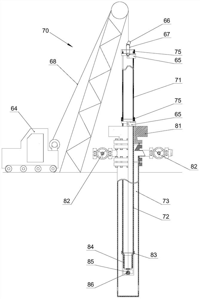
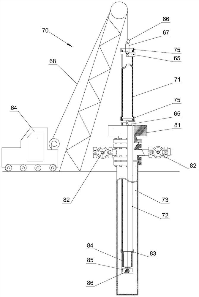
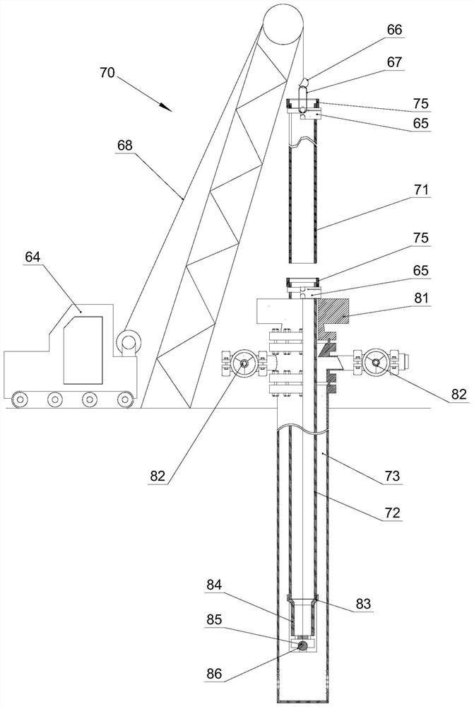
[0078]The present invention provides a pipe string extraction structure, including: an upper oil pipe 71, a lower oil pipe 72, an oil pipe coupling 75, a lifting mechanism 60 and the above-mentioned liquid drainage device in the extraction pipe string, and the upper oil pipe 71 and the lower oil pipe 72 pass through The oil pipe collar 75 is connected; the rubber plate 20 in the liquid drainage device of the lifting string is set outside the upper oil pipe 71 and the oil pipe collar 75; the lifting mechanism 60 is connected with the upper oil pipe 71 for lifting the upper oil pipe 71 upward.

[0079] Using the string lifting structure, the liquid in the string can be sealed and drained to the designated area, which alleviates the technical problem in the prior art that the liquid in the tubing will pour out during the construction of the string of pulling out tubing, and achieve The purpose of the oil well workover operation is to prevent the liquid from falling to the ground w...

Embodiment 3

[0088] The present invention provides a method for pulling out a pipe string, using the above-mentioned pipe string internal liquid drainage device, the pipe string lifting method includes: step S, pulling out 20 sets of rubber sheets in the pipe string internal liquid drainage device Set outside the upper oil pipe 71 and the oil pipe collar 75; step S, lift the upper oil pipe 71 upward, the upper oil pipe 71 moves upward relative to the rubber plate 20, and the liquid in the upper oil pipe 71 flows into the rubber plate 20; step S, the rubber plate 20 The liquid inside is discharged outward through the liquid discharge through hole 201 ; Step S, the upper oil pipe 71 moves upwards and separates from the rubber plate 20 .

[0089] Using the method for pulling out the tubing string, the liquid in the tubing string can be sealed and drained to a designated area, which alleviates the technical problem in the prior art that the liquid in the tubing will pour out when the tubing str...


PUM


Abstract

The invention provides a drainage device for liquid in a pulling-out tubular column, a tubular column pulling-out structure and a tubular column pulling-out method. The drainage device for the liquid in the pulling-out tubular column comprises a first fan-shaped column body, a second fan-shaped column body and a third fan-shaped column body, the second fan-shaped column body is hinged to the first fan-shaped column body; the rubber plates are arranged on the inner wall of the first fan-shaped column body and the inner wall of the second fan-shaped column body, the first fan-shaped column body and the second fan-shaped column body can relatively rotate to a closed state, and in the closed state, the first fan-shaped column body and the second fan-shaped column body drive the rubber plates to form a closed barrel shape in a surrounding mode; a liquid drainage through hole is formed in the rubber plate; and the locking mechanism can lock the first fan-shaped column body and the second fan-shaped column body in the folding state. According to the invention, the technical problem in the prior art that liquid in the oil pipe can be poured outwards when the oil pipe column is pulled out for construction is solved.

Description

technical field [0001] The invention relates to the field of petroleum engineering, in particular to a liquid drainage device in a pipe string, a pipe string lifting structure and a pipe string pulling out method. Background technique [0002] With the prolongation of the production time of deep well pump oil wells, workover operations are required due to failures or measures; in the construction procedures of workover operations, the important link is to pull out the tubing string from the downhole of the oil well. The bottom end of the tubing string is connected to the deep well pump, and the bottom end of the deep well pump is a fixed Val seat seal. In actual production, failures such as oil drain not opening, piston stuck in the work barrel, and sucker rod breakage often occur. At this time, the liquid in the tubing string remains in the pipe and cannot be leaked. , when the oil pipe thread is removed, a liquid column about 10 meters high in the oil pipe will form a liq...

Claims


Application Information

Patent Timeline
Patent Type & Authority Applications(China)
IPC IPC(8): E21B33/08E21B19/00E21B19/16E21B17/02
CPCE21B33/08E21B19/00E21B19/16E21B17/02
Inventor 杨波袁勇陈伟东杨茜婷王瑞英杨也波佟晓欢兰盛川张蕾
Owner PETROCHINA CO LTD
Why Eureka
Try Eureka