Rotary lifting mechanism driven by straight stroke actuator

A lifting mechanism and straight stroke technology, applied in the direction of engine components, shaking/oscillating/vibrating mixers, mixers, etc., can solve the problems of complex structure of air motors, high cost of air motors, and easy failures, etc., to achieve simple structure, High rotational torque and friction reduction effect

Pending Publication Date: 2022-03-29
BEIJING AEROSPACE PETROCHEM TECH & EQUIP ENG CORP LTD
View PDF9 Cites 0 Cited by
  • Summary
  • Abstract
  • Description
  • Claims
  • Application Information

AI Technical Summary

Problems solved by technology

The main problem of this method is that the structure of the air motor is more complicated than that of the cylinder, it is prone to failure, and the cost of the air motor is relatively high
[0006] Another is to use the electric head as the power source to realize the rotation and lifting of the valve core, but the structure is also complex and prone to failure, and the torque is much lower than that of the pneumatic mechanism.

Method used


Image

  • Rotary lifting mechanism driven by straight stroke actuator

Examples


Embodiment

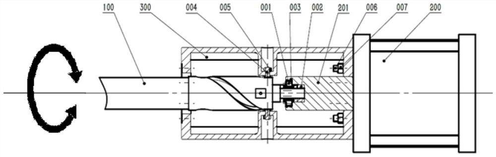
[0023] refer to figure 1 , shows a schematic structural view of a rotary lifting mechanism driven by a linear actuator provided in an embodiment of the present invention.

[0024] Such as figure 1 As shown, the rotary lifting mechanism driven by the linear stroke actuator provided by the embodiment of the present invention may include: an actuator member 100, a needle roller with a flange and a double-direction thrust cylindrical roller bearing 001, a lock nut 002, a bolt 003, Straight stroke actuator 200, straight stroke push rod 201, bracket barrel 300, bolt type roller needle bearing 004, nut 005, stud 006, nut 007.

[0025] The bracket cylinder 300 and the linear stroke actuator 200t are fixed on the same axis. The bolt type roller needle roller bearing 004 is assembled on the bracket cylinder 300 through the nut 005. Cooperate.

[0026] The combined needle roller and bidirectional thrust cylindrical roller bearing 001 with flange is a ZARF type standard bearing, which ...


PUM


Abstract

The embodiment of the invention discloses a rotary lifting mechanism driven by a straight stroke actuator, which comprises an actuating component, a straight stroke push rod, a two-way thrust cylindrical roller combination bearing, the straight stroke actuator, a bolt type roller needle bearing and a support cylinder, the straight stroke actuator and the bolt type roller needle bearing are fixed on the support cylinder, a spiral groove is formed in the execution component, the bidirectional thrust cylindrical roller combination bearing is fixed at the protruding end of the execution component, and the support cylinder and the straight stroke actuator are fixed on the same axis. When the straight stroke push rod does axial linear motion under the action of the straight stroke actuator, the execution component does rotary lifting motion under the action of the spiral groove and the bolt type roller needle bearing. According to the embodiment of the invention, the execution component can rotate while performing linear motion.

Description

technical field [0001] The invention relates to the technical field of structural design, in particular to a rotary lifting mechanism driven by a linear actuator. Background technique [0002] This mechanism can be used in equipment that needs to convert lifting motion into rotary lifting motion, and has wide application prospects in petrochemical, chemical fiber and other industries, especially when the viscosity of the medium is high and some raw materials are easy to solidify and crystallize. Driven by the linear actuator, the rotating and lifting movement of the actuator is driven to achieve the effect of lifting and stirring. Typically used in the transmission system of plunger valves. [0003] The plunger valve is often used in the chemical industry where the medium is a melt, and it mainly plays the role of a switch. Due to the high viscosity of the medium, and some melts are easy to solidify and crystallize, it is required that the spool of the plunger valve can pl...

Claims


Application Information

Patent Timeline
Patent Type & Authority Applications(China)
IPC IPC(8): F16K31/44F16K31/122B01F31/44B01F31/441
CPCF16K31/44F16K31/122
Inventor 李强丁英仁郑平阳郭玉生苏祥张博文晁继阳
Owner BEIJING AEROSPACE PETROCHEM TECH & EQUIP ENG CORP LTD
Why Eureka
Try Eureka