Round hole polishing and deburring mechanism

A technology of deburring mechanism and round hole, applied in the field of machining, can solve the problems of inconvenience for stable polishing of parts holes of different sizes, inconvenience for positioning and polishing of multiple parts holes, etc.

Active Publication Date: 2022-04-01
漳州市盈励塑胶制品有限公司
View PDF5 Cites 1 Cited by
  • Summary
  • Abstract
  • Description
  • Claims
  • Application Information

AI Technical Summary

Problems solved by technology

[0004] The products in the above patents can go deep into the inner wall of the hole to remove burrs and sweep out fine chips, but it is not convenient for simultaneous positioning and polishing of multiple parts holes, and it is not convenient for stable polishing of parts holes of different sizes

Method used


Image

  • Round hole polishing and deburring mechanism
  • Round hole polishing and deburring mechanism
  • Round hole polishing and deburring mechanism

Examples


Embodiment Construction

[0032] In order to facilitate the understanding of the present invention, the present invention will be described more fully below with reference to the relevant drawings, in which several embodiments of the present invention are shown, but the present invention can be realized in different forms, and is not limited to the text described On the contrary, these embodiments are provided to make the disclosure of the present invention more thorough and comprehensive.

[0033] It should be noted that when an element is said to be "fixed on" another element, it can be directly on the other element or there can be an intervening element, and when an element is said to be "connected" to another element, it can be Directly connected to another element or possibly intervening elements at the same time, the terms "vertical," "horizontal," "left," "right," and similar expressions are used herein for purposes of illustration only.

[0034] Unless otherwise defined, all technical and scien...


PUM


Abstract

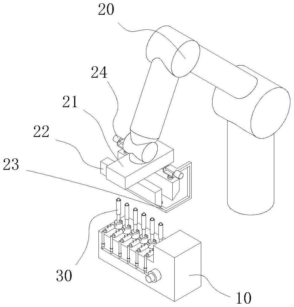
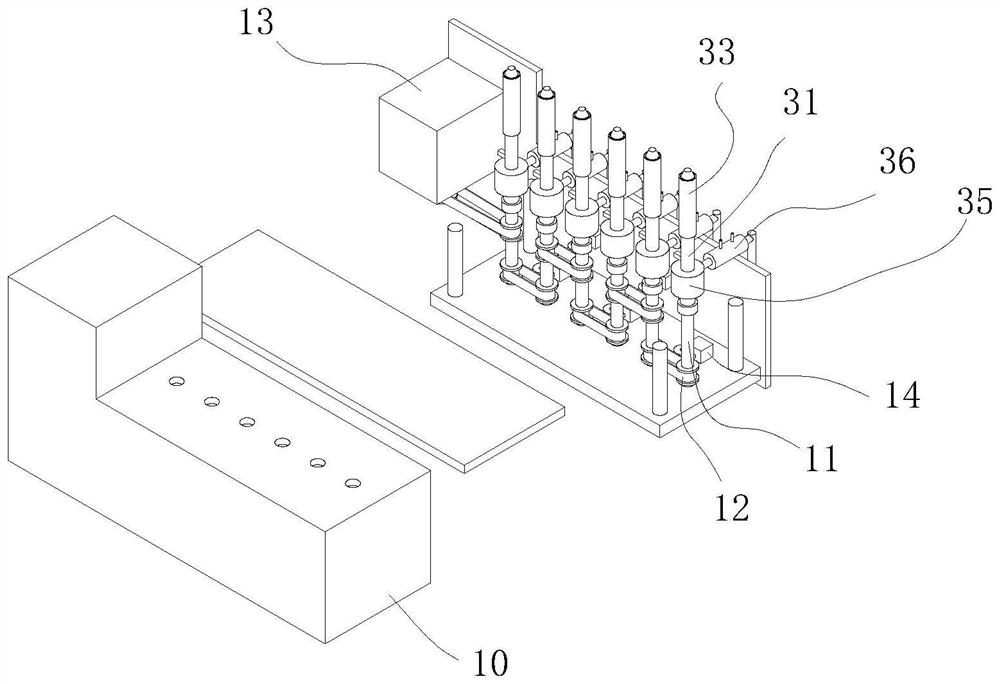
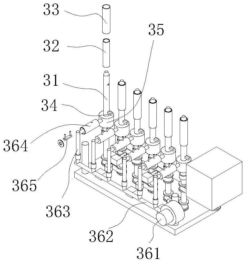
The round hole polishing and deburring mechanism comprises a box body and a mechanical arm located on one side of the box body, a plurality of rotating shafts are arranged in the box body in a linear array mode, and a transmission part is arranged between every two adjacent rotating shafts; a self-adaptive polishing device is arranged at the top end of the rotating shaft and comprises a shaft pipe, an air bag component arranged on the outer wall of the shaft pipe in a sleeving mode and communicating with the air inlet cavity and the air outlet cavity, an elastic polishing sleeve arranged outside the air bag component in a sleeving mode and an airflow sweeping component arranged at the bottom of the side wall of the shaft pipe, and the interior of the shaft pipe is divided into an air inlet cavity and an air outlet cavity through a partition plate. The air inlet component is arranged on the upper surface of the box body, and the temperature control air supply component is arranged on the side wall of the box body; a clamping jaw is arranged at the executing end of the mechanical arm, a part containing frame is arranged at the bottom of the clamping jaw, and a plurality of part hole positioning components are arranged on the part containing frame. According to the round hole polishing mechanism, a plurality of part holes can be conveniently positioned and polished at the same time, and the part holes of different sizes can be conveniently and stably polished.

Description

technical field [0001] The invention mainly relates to the technical field of machining, in particular to a circular hole polishing and deburring mechanism. Background technique [0002] The polishing and deburring of parts holes is often a difficult point in mechanical processing. Manual polishing is time-consuming and laborious with poor effect, and the stability of mechanical polishing is poor. [0003] According to a kind of round hole workpiece deburring tooling provided by the patent literature with the application number CN201820011237.3, it can be known that the product includes a body, a motor is fixed in the interlayer on one side of the body, and the output end of the motor is fixed to one end of the lead screw. The screw and the nut pair are connected by threads, the top of the nut pair is welded and fixed to the bottom of the workbench, the top of the workbench is fixed with a fixture, one side of the workbench is fixed with a support plate, and the bottom of th...

Claims


Application Information

Patent Timeline
IPC IPC(8): B24B9/00B24B29/04B24B55/02B24B41/06B24B41/00B24B47/12
CPCY02P70/10
Inventor 苏军陈飞龙吴俊杰
Owner 漳州市盈励塑胶制品有限公司
Why Eureka
Try Eureka