Optical polishing material

A polishing material and optical technology, applied in the field of polishing materials, can solve the problems of polyurethane polishing pads such as hard, brittle, lack of toughness and elasticity, etc., and achieve the effect of not easy passivation, good wear resistance, and no deformation on the surface

Inactive Publication Date: 2019-04-26
CHANGCHUN A&Z SCI CO LTD
View PDF4 Cites 2 Cited by
  • Summary
  • Abstract
  • Description
  • Claims
  • Application Information

AI Technical Summary

Problems solved by technology

[0005] In view of this, the present invention provides an optical polishing material to solve the technical problems of polyurethane polishing pads in the prior art, which are hard and brittle, and lack toughness and elasticity.

Method used


Image

  • Optical polishing material
  • Optical polishing material
  • Optical polishing material

Examples


Embodiment 1

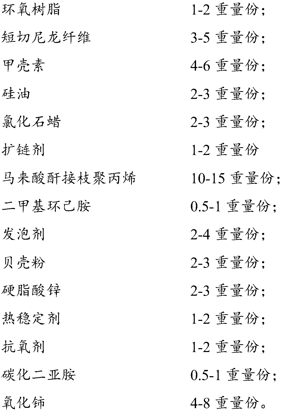
[0029] The optical polishing material is composed of 100 parts by weight of polyether polyol, 100 parts by weight of diisocyanate, 1 part by weight of bisphenol A type epoxy resin, 3 parts by weight of chopped nylon fiber (4mm), 4 parts by weight of chitin, and 2 parts by weight of silicone oil 2 parts by weight of chlorinated paraffin, 1 part by weight of ethylene glycol, 10 parts by weight of maleic anhydride grafted polypropylene, 0.5 parts by weight of dimethylcyclohexylamine, 2 parts by weight of acetone, 2 parts by weight of shell powder (50 μm) , 2 parts by weight of zinc stearate, 1 part by weight of tris(2,4-di-tert-butylphenyl) phosphite, 10101 parts by weight of antioxidant, 0.5 parts by weight of carbodiimide and cerium oxide (80 μm) 8 parts by weight.

Embodiment 2

[0031] Optical polishing material is made of 100 parts by weight of polyether polyol, 100 parts by weight of diisocyanate, 1.5 parts by weight of bisphenol A epoxy resin, 4 parts by weight of chopped nylon fiber (4mm), 5 parts by weight of chitin, and 2.5 parts by weight of silicone oil 2.5 parts by weight of chlorinated paraffin, 1.5 parts by weight of ethylene glycol, 12 parts by weight of maleic anhydride grafted polypropylene, 0.8 parts by weight of dimethylcyclohexylamine, 3 parts by weight of acetone, 2.5 parts by weight of shell powder (50 μm) , 2.5 parts by weight of zinc stearate, 1.5 parts by weight of tris(2,4-di-tert-butylphenyl) phosphite, 10101.5 parts by weight of antioxidant, 0.8 parts by weight of carbodiimide and cerium oxide (100 μm) 6 parts by weight.

Embodiment 3

[0033] The optical polishing material is composed of 100 parts by weight of polyether polyol, 100 parts by weight of diisocyanate, 2 parts by weight of bisphenol A epoxy resin, 5 parts by weight of chopped nylon fiber (4mm), 6 parts by weight of chitin, and 3 parts by weight of silicone oil 3 parts by weight of chlorinated paraffin, 2 parts by weight of ethylene glycol, 15 parts by weight of maleic anhydride grafted polypropylene, 1 part by weight of dimethylcyclohexylamine, 4 parts by weight of acetone, 3 parts by weight of shell powder (50 μm) , 3 parts by weight of zinc stearate, 2 parts by weight of tris(2,4-di-tert-butylphenyl) phosphite, 2 parts by weight of antioxidant 1010, 1 part by weight of carbodiimide and cerium oxide (120 μm) 8 parts by weight.


PUM

PropertyMeasurementUnit
lengthaaaaaaaaaa
particle diameteraaaaaaaaaa

Abstract

The invention relates to an optical polishing material, belongs to the technical field of polishing materials and solves the technical problem that a polyurethane polishing pad is hard and brittle andis lack of toughness and elasticity in the prior art. The optical polishing material is prepared from components in parts by weight as follows: 100 parts of polyether polyol, 100 parts of diisocyanate, 1-2 parts of bisphenol A epoxy resin, 3-5 parts of chopped nylon fiber, 4-6 parts of chitin, 2-3 parts of silicone oil, -3 parts of chlorinated paraffin, 1-2 parts of ethylene glycol, 10-15 parts of maleic anhydride grafted polypropylene, 0.5-1 part of dimethylcyclohexylamine, 2-4 parts of acetone, 2-3 parts of shell powder, 2-3 parts of zinc stearate, 1-2 parts of tris(2,4-ditert-butylphenyl)phosphite, 1-2 parts of antioxidant 1010, 0.5-1 part of carbodiimide and 4-8 parts of cerium oxide. The optical polishing material has high tensile strength and good rebound resilience, wear resistance and die assembly performance, and is not prone to passivation.

Description

technical field [0001] The invention belongs to the technical field of polishing materials, and in particular relates to an optical polishing material. Background technique [0002] Glass has a long history and stable properties. It is an excellent material that has stood the test of time. It can not only be used for decoration, but also play an important role in various optical instruments, and can even be used to help buildings save energy and reduce noise. The surface of the glass is not smooth and clear enough, and it needs to undergo necessary surface polishing before being used, so polishing materials are produced. [0003] In the prior art, the polishing materials used in the early stage mainly include titanium oxide, iron oxide or silicon dioxide; in recent years, with the rapid development of electronic information technology, lenses, flat glass, liquid crystal displays (LCD), glasses, optical components The demand for glass substrates such as ceramic materials and...

Claims


Application Information

Patent Timeline
Patent Type & Authority Applications(China)
IPC IPC(8): C08L75/08C08L77/00C08L83/04C08L91/06C08L51/06C08K13/02C08K3/26C08K5/098C08K5/526C08K5/134C08K3/22C08J9/14C08G18/58C08G18/48C08G18/64C08G18/32
CPCC08G18/3206C08G18/3234C08G18/4045C08G18/48C08G18/58C08G18/6484C08J9/0023C08J9/0028C08J9/0038C08J9/0061C08J9/0066C08J9/0085C08J9/142C08J2203/12C08J2375/08C08J2451/06C08J2477/00C08J2483/04C08J2491/06C08K5/098C08K5/1345C08K5/526C08K13/02C08K2003/2213C08K2003/265
Inventor 王杰郇彦
Owner CHANGCHUN A&Z SCI CO LTD
Why Eureka
Try Eureka