Eureka AIR delivers breakthrough ideas for toughest innovation challenges, trusted by R&D personnel around the world.

Beam column joint template

A beam-column joint and beam formwork technology, which is applied to formwork/formwork/work frame, on-site preparation of building components, construction, etc., can solve the problem that the gap of the joint is not easy to be controlled within the allowable range of the specification, and the formwork is prone to displacement. , uneven concrete surface and other problems, to ensure safe use function and visual quality, reduce the necking of the column section, and reduce the phenomenon of mold expansion.

Pending Publication Date: 2022-04-01
CHINA HUAYE GROUP
View PDF6 Cites 0 Cited by
  • Summary
  • Abstract
  • Description
  • Claims
  • Application Information

AI Technical Summary

Problems solved by technology

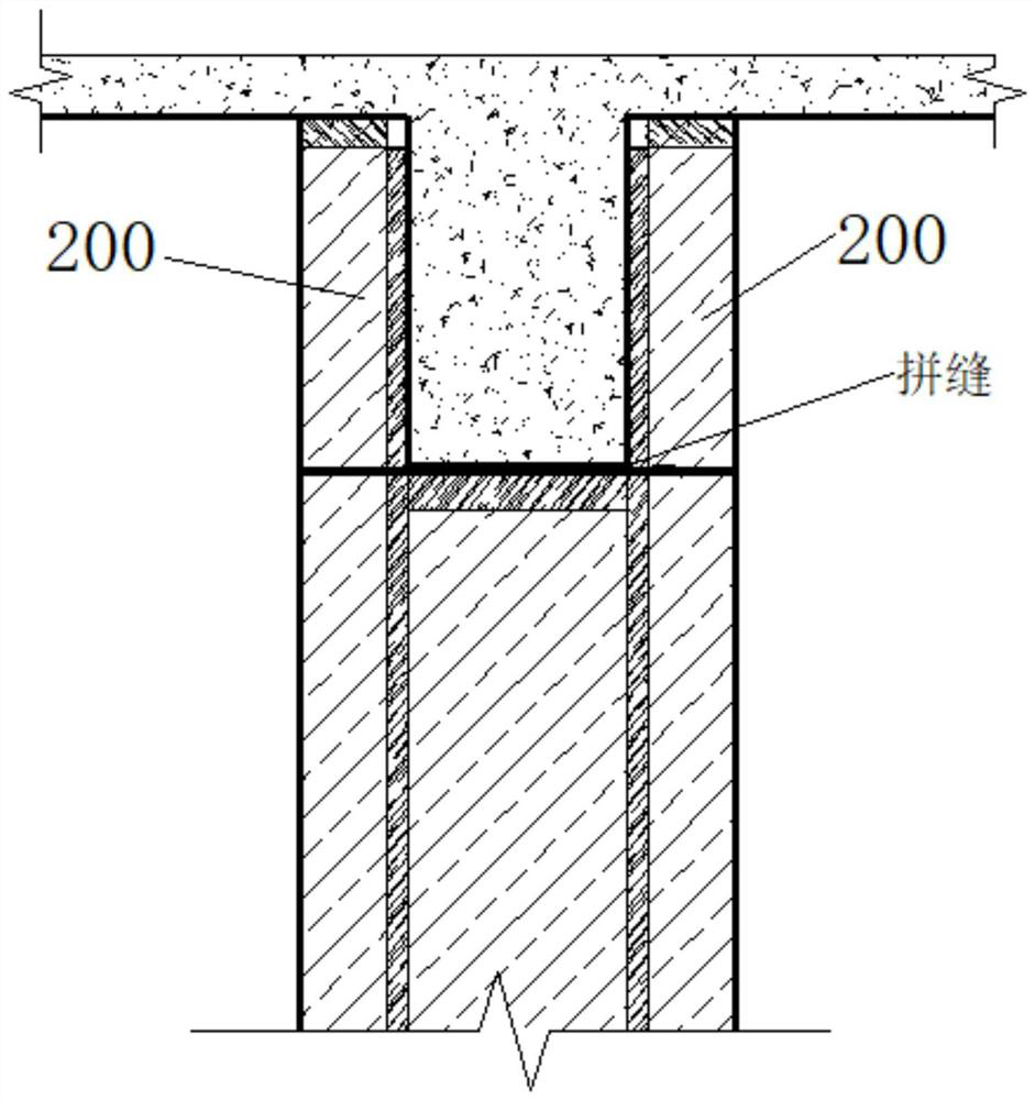
[0005] (1) On the side of each column, there are two small formwork joints with the lower formwork. The construction efficiency is low, and the formwork joints are many. The gap between the joints is not easy to control within the allowable range of the specification, and the joints are prone to leakage Phenomenon that affects the construction quality of concrete
[0006] (2) The small formwork is easy to be uneven at the joints, and the concrete surface is also uneven after pouring the concrete, which affects the molding quality of the concrete
[0007] (3) The small formwork is not easy to strengthen. When pouring concrete, the formwork is prone to displacement. Displacement to the inside of the column will easily cause the necking of the column section, and outward displacement will easily cause the column to expand, which will affect the safe use of the column and greatly affect the column. Perceptual quality of

Method used


Image

  • Beam column joint template
  • Beam column joint template
  • Beam column joint template

Examples


Embodiment Construction

[0027] Embodiments of the present invention will be described below with reference to the accompanying drawings. Those skilled in the art would recognize that the described embodiments can be modified in various ways or combinations thereof without departing from the spirit and scope of the invention. Accordingly, the drawings and description are illustrative in nature and not intended to limit the scope of the claims. Also, in this specification, the drawings are not drawn to scale, and like reference numerals denote like parts.

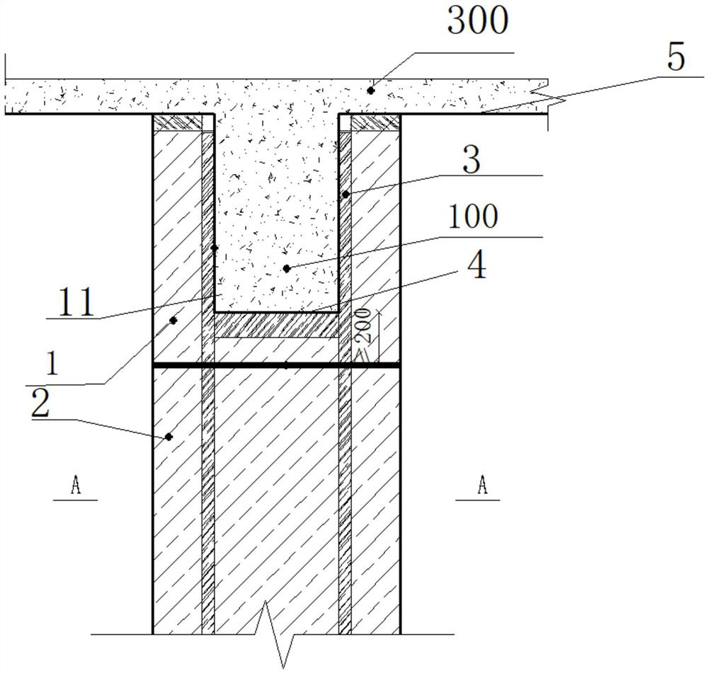
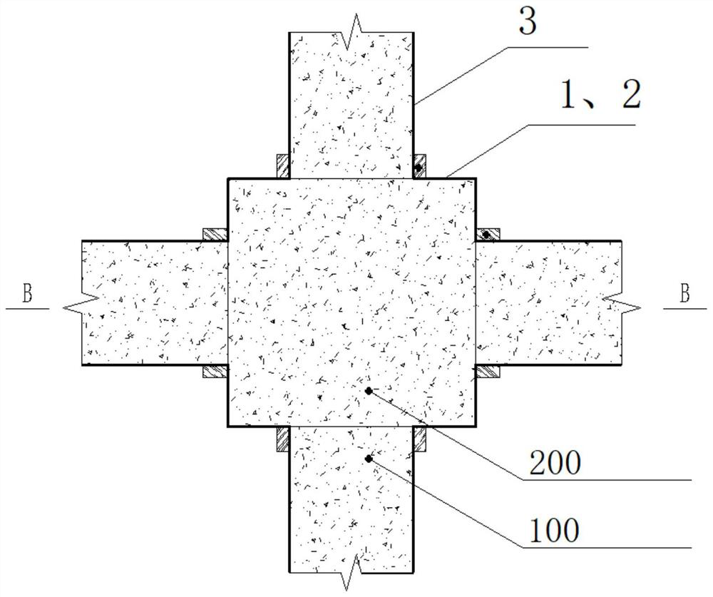
[0028] The beam-column joint formwork of this embodiment includes a column side formwork and a beam formwork, such as figure 2 As shown, each column side formwork includes an upper column side formwork 1 and a lower column side formwork 2, and the formwork encloses the pouring space for beams and columns. Among them, the upper column side formwork 1 and the lower column side formwork 2 are formworks on the same column side along the cross-section...


PUM


Abstract

The beam-column joint formwork comprises column side formworks and beam formworks, a pouring space of a beam column is defined by the column side formworks and the beam formworks, each column side formwork comprises an upper column side formwork and a lower column side formwork, each upper column side formwork is provided with a through hole consistent with the cross section of a beam in shape, and each lower column side formwork is provided with a through hole matched with the cross section of the beam in shape. The upper column side template is provided with a through hole, so that the upper column side template forms a communicated pouring space between the through hole position and the beam template, and the height of the lower end of the upper column side template is lower than the elevation of the beam bottom. The mortar leakage phenomenon can be reduced, the surface of concrete is smooth, and the forming quality of the concrete is good. And the phenomena of necking and mold expansion of the cross section of the column are reduced.

Description

technical field [0001] The invention relates to the technical field of building construction, in particular to a beam-column joint template. Background technique [0002] Beam-column joints of frame structures refer to the intersections of beams and columns. The most commonly used formwork materials are wood formwork (bamboo plywood, plywood, etc.), and the side of the column formwork is supplemented by square wood backing and column hoops. The side of the beam formwork Square wood girders, steel pipe girders (back corrugated) and scaffolding support system are used for formwork support, and the bottom of the floor and beam formwork is formed by square wood girders, steel pipe girders and scaffolding support system. [0003] Among them, the formwork at the top of the beam-column node of the frame structure is also made of wooden formwork, and the outside of the formwork is reinforced with square wood backing and column hoops. The formwork generally adopts a formwork with a ...

Claims


Application Information

Patent Timeline
Patent Type & Authority Applications(China)
IPC IPC(8): E04G13/00E04G13/02E04G13/04
Inventor 乌凤文赵志杰张博豆素芬
Owner CHINA HUAYE GROUP
Why Eureka
Eureka Blog
Learn More