High-efficient low-order mode transverse flow CO2 laser

A laser and low-order mode technology, which is applied in lasers, laser components, phonon exciters, etc., can solve the problems of reduced laser output power and photoelectric conversion efficiency, heating of components such as transformer inductance, and low utilization of active regions. Achieve high photoelectric conversion efficiency, increase output power, and expand the effective gain area

Inactive Publication Date: 2005-08-10
SHANGHAI INST OF OPTICS & FINE MECHANICS CHINESE ACAD OF SCI +1
View PDF0 Cites 1 Cited by
  • Summary
  • Abstract
  • Description
  • Claims
  • Application Information

AI Technical Summary

Problems solved by technology

If you want to obtain low-order mode oscillation output, it is usually by adding a diaphragm in the cavity. Under the stable cavity structure, for TEM 00 Model ~ TEM 11 Mode, the spot diameter is about φ10~φ22mm, the utilization rate of the entire active area is very low, with the decrease of the transverse mode order, the laser output power and photoelectric conversion efficiency are reduced, so some use the folded cavity method, as far as possible Utilize active region volume to obtain high power low order mode output
Due to the negative resistance effect of DC gas discharge, in order to stabilize the glow discharge, a current-limiting resistor is generally connected in series in the discharge circuit. The resistance of the current-limiting resistor is relatively large, about a few kΩ, so the power consumption in the circuit is relatively high. In addition, the high-voltage DC power supply of previous products often adopts thyristor voltage regulation or thyristor module voltage regulation, which is a 50Hz power frequency step-up rectification technology. cooling device
Many factors make the electro-optical conversion efficiency of the final equipment very low. In the current situation of relatively tight power resources, it is very necessary to improve the electro-optic conversion efficiency of the equipment and reduce the cost of use.

Method used


Image

  • High-efficient low-order mode transverse flow CO2 laser
  • High-efficient low-order mode transverse flow CO2 laser

Examples


Embodiment Construction

[0018] The present invention will be further described below in conjunction with the embodiments and accompanying drawings, but the protection scope of the present invention should not be limited by this.

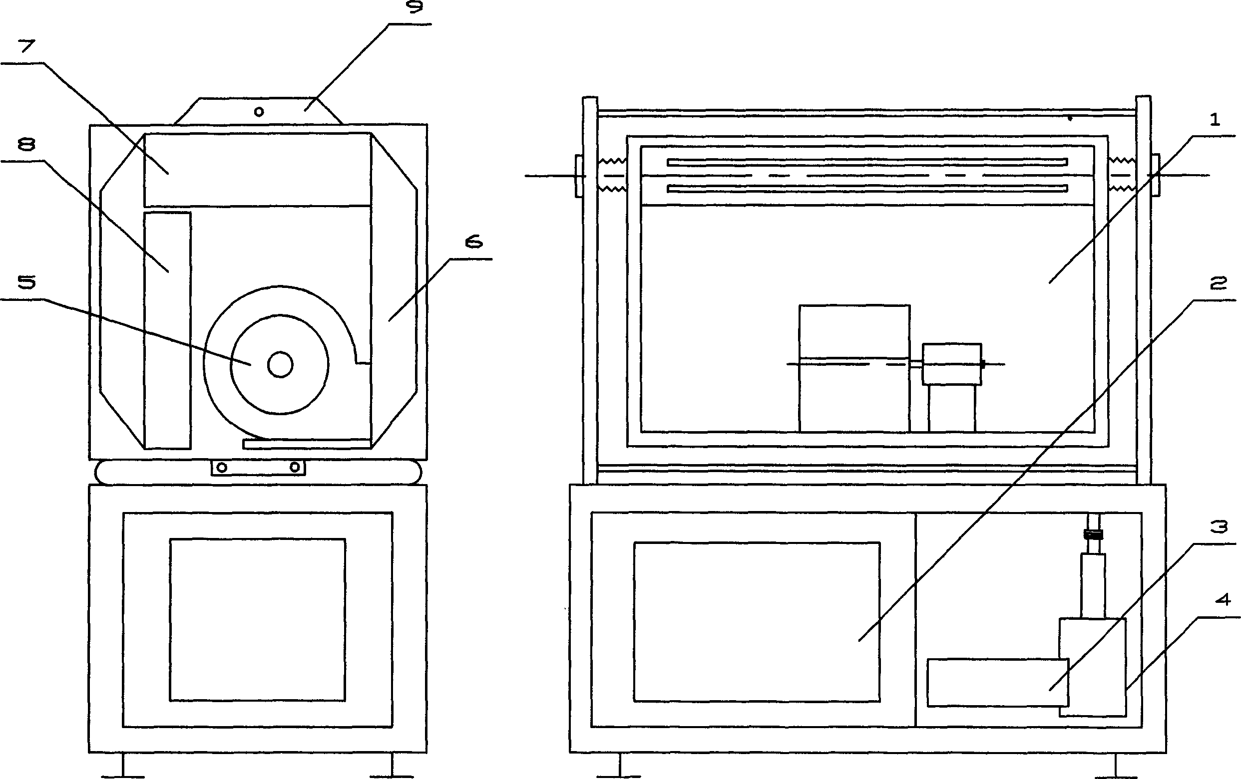
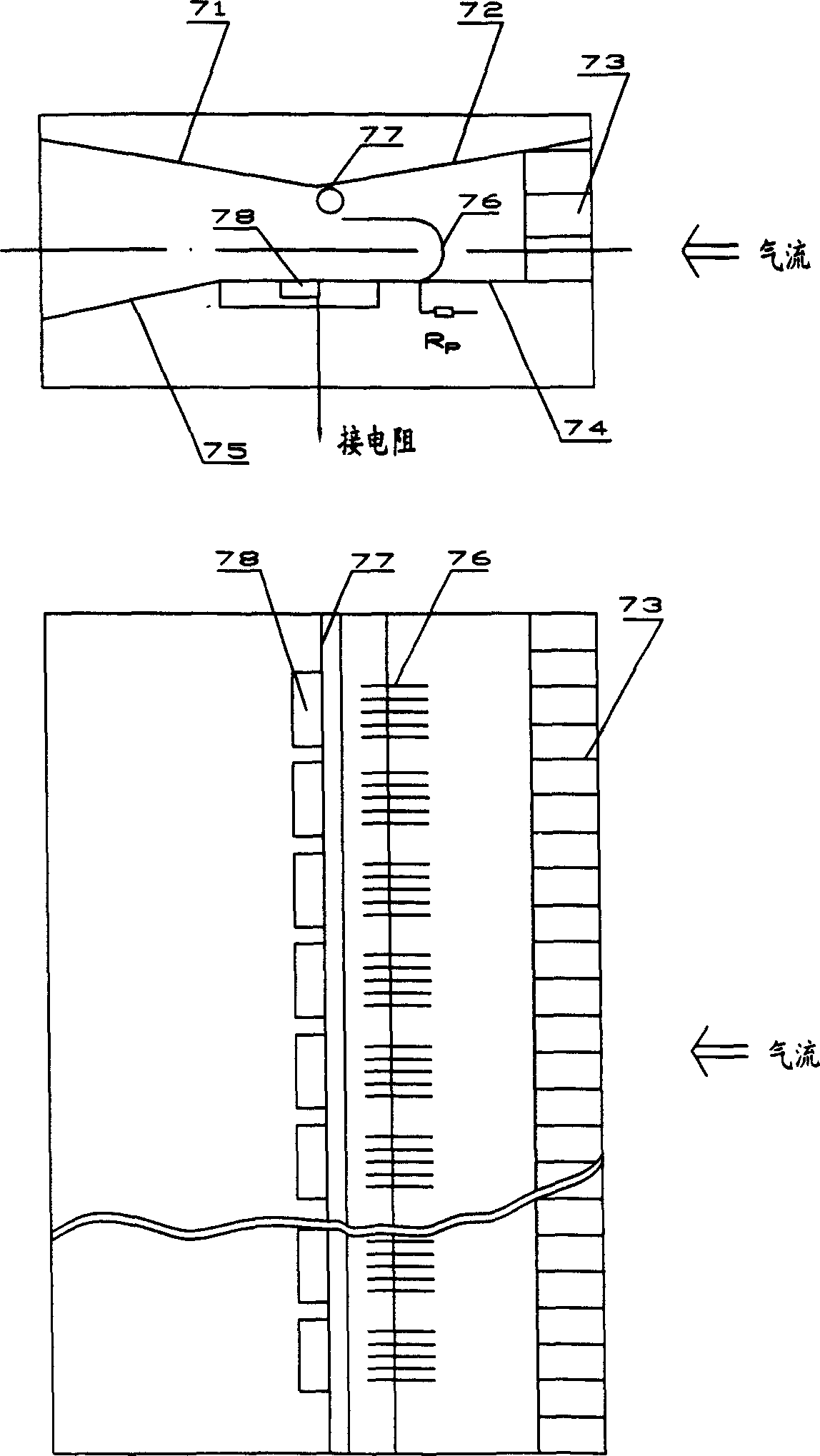
[0019] see first figure 1 and figure 2 , figure 1 is a schematic diagram of the laser structure of the embodiment of the present invention, figure 2 It is a structural schematic diagram of the gas discharge chamber of the present invention. As can be seen from the figure, the high-efficiency low-order mode CO of the present invention 2 The laser is composed of a laser head 1, a high-power switching power supply 2, a resistance box 3 and an air extraction system 4 placed in a box, the laser head 1 is placed above the box, the switching power supply 2, the resistance box 3 and air extraction system 4 are respectively placed in the lower part of the box, and the laser head 1 is composed of a centrifugal fan 5, an air duct 6, a discharge chamber 7, a heat exchanger 8, an ...


PUM

PropertyMeasurementUnit
electrical resistanceaaaaaaaaaa

Abstract

The disclosed integrated device is composed of laser head, DC power source in high voltage, resistor and gas-extraction system. The laser head consists of blower fan, air passage, arc chamber, heat exchanger and optical cavity. Each part adopted in module structure is assembled in a sealed square box body. Discharge excitation for laser is DC discharge. Electrode structure adopted in sheet type electrode with wide anode bar makes discharge zone match to mode volume of cavity. Constant current technique in low resistance is adopted to reduce electric loss. Power source of using high frequency switch increases conversion efficiency for transforming and delivering electric power, and optical cavity is optimized to reach output of laser in low order modulo under high electro-optical conversion efficiency and high output power.

Description

technical field [0001] The present invention relates to CO 2 Lasers, especially a high-efficiency low-order mode cross-flow CO 2 Laser, which has high electro-optical conversion efficiency, low-order mode oscillation output, and compact structure, is especially suitable for laser welding and cutting. Background technique [0002] DC discharge of cross-flow CO 2 The laser adopts three-axis orthogonal excitation technology, that is, the direction of airflow, discharge direction and light oscillation direction are perpendicular to each other, so the discharge channel (section) is relatively large, generally up to 25×40mm, and the large-size cavity mirror is selected to directly transmit the oscillation light energy in the cavity. Coupled out to obtain multi-mode output laser. In general, the direct electro-optical conversion efficiency is around 15%. If you want to obtain low-order mode oscillation output, it is usually by adding a diaphragm in the cavity. Under the stable ...

Claims


Application Information

Patent Timeline
Patent Type & Authority Applications(China)
IPC IPC(8): H01S3/00
Inventor 归振兴沈华勤冯建中柳月英沈晖陆鸿飞
Owner SHANGHAI INST OF OPTICS & FINE MECHANICS CHINESE ACAD OF SCI
Why Eureka
Try Eureka