Flow battery stack structure

A technology for flow batteries and battery electrodes, which is applied to fuel cells, regenerative fuel cells, and components of fuel cells, etc., can solve problems such as excessive flow resistance, unfavorable electrolyte flow, and decreased system efficiency, and achieve improved flow power. , the effect of increasing the electrochemical reaction rate and increasing the pressure

Pending Publication Date: 2022-04-01
华秦储能技术有限公司
View PDF0 Cites 0 Cited by
  • Summary
  • Abstract
  • Description
  • Claims
  • Application Information

AI Technical Summary

Problems solved by technology

However, reducing the distance between electrodes and increasing the replenishment of electrolyte is actually a contradictory design. Too small electrode spacing will cause excessive flow resistance, and the flow of electrolyte will not be utilized.
For this reason, only the pump with higher power is replaced, which will cause the efficiency of the system to drop

Method used


Image

  • Flow battery stack structure
  • Flow battery stack structure
  • Flow battery stack structure

Examples


Embodiment

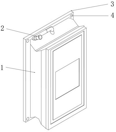
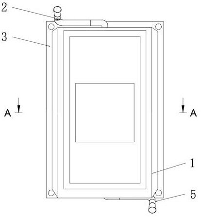
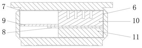
[0031] Such as figure 1 , 2 , 3, 4, 5, 6, and 7, the embodiment of the present invention provides a flow battery stack structure, including a battery electrode frame 1, and an installation cavity 6 is opened inside the battery electrode frame 1, The upper end of the battery electrode frame 1 is fixedly equipped with an electrolyte outlet flow channel 2, one end of the electrolyte outlet flow channel 2 communicates with the interior of the installation cavity 6, and the other end of the electrolyte outlet flow channel 2 is connected to the The electrolyte storage tank is connected, and the end of the battery electrode frame 1 away from the electrolyte outlet flow channel 2 is installed with an electrolyte inlet flow channel 5, and the electrolyte inlet flow channel 5 includes a connecting pipe 501, a feed port joint 502 and installation pipe 503, the connecting pipe 501 includes a connecting pipe main body 501a, one end of the connecting pipe main body 501a is fixedly connecte...


PUM


Abstract

The present invention provides a flow battery stack structure, and relates to the technical field of flow battery structures, the flow battery stack structure comprises a battery electrode frame, the battery electrode frame is internally provided with a mounting cavity, and the upper end of the battery electrode frame is fixedly provided with an electrolyte outlet flow channel; one end of the electrolyte outlet flow channel is communicated with the interior of the mounting cavity, the other end of the electrolyte outlet flow channel is communicated with the electrolyte storage tank, an electrolyte inlet flow channel is mounted at one end, far away from the electrolyte outlet flow channel, of the battery electrode frame body, and the electrolyte inlet flow channel comprises a connecting pipe, a feeding hole joint and a mounting pipe; and the connecting pipe comprises a connecting pipe main body, and after the electrolyte passes through the boss, the inner diameter of the boss is gradually increased from inside to outside, so that the pressure when the electrolyte passes through is increased, the flowing speed of the electrolyte is increased, the electrolyte quickly passes through the mounting pipe and enters the mounting cavity for reaction, and then the electrochemical reaction rate is increased.

Description

technical field [0001] The invention relates to the technical field of liquid flow battery structures, in particular to a liquid flow battery stack structure. Background technique [0002] With the rapid development of social economy and science and technology, the consumption of energy has increased significantly. The development and utilization of renewable energy is an important choice for the development of strategic emerging industries and the transformation of economic development mode. The large-scale development and utilization of renewable energy will significantly reduce the consumption of fossil energy resources for economic development and reduce the damage to the environment. At the same time, renewable energy is a fast-growing strategic emerging industry. The development of renewable energy plays a significant role in stimulating the development of high-end equipment manufacturing-related industries, and is of great significance in promoting the upgrading of in...

Claims


Application Information

Patent Timeline
Patent Type & Authority Applications(China)
IPC IPC(8): H01M8/18H01M8/0258H01M8/0273H01M8/0293
CPCY02E60/50
Inventor 郑建伟王兆哲方明程杰
Owner 华秦储能技术有限公司
Why Eureka
Try Eureka