Shell assembly, manufacturing method thereof and electronic equipment

A shell component and shell technology, which is applied in the direction of shell/cabinet/drawer components, optics, instruments, etc., can solve the problem that the shell cannot meet the growing demand, achieve bright colors, meet The effect of using demand and improving brightness

Pending Publication Date: 2022-04-01
GUANGDONG OPPO MOBILE TELECOMM CORP LTD
View PDF7 Cites 0 Cited by
  • Summary
  • Abstract
  • Description
  • Claims
  • Application Information

AI Technical Summary

Problems solved by technology

[0002] Due to the requirements of appearance and function, many production and living tools, such as electronic equipment, household appliances, etc., have shells. With the improvement of users' requirements for the appearance of various equipment, shells with only a single function are no longer available. Ability to meet growing demand

Method used


Image

  • Shell assembly, manufacturing method thereof and electronic equipment
  • Shell assembly, manufacturing method thereof and electronic equipment
  • Shell assembly, manufacturing method thereof and electronic equipment

Examples


Embodiment 1

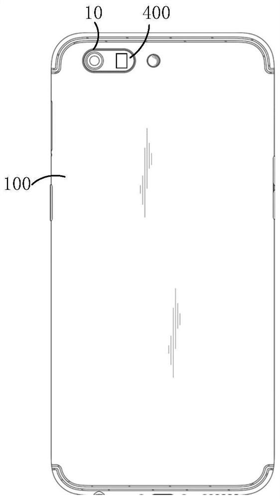
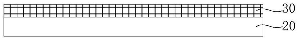
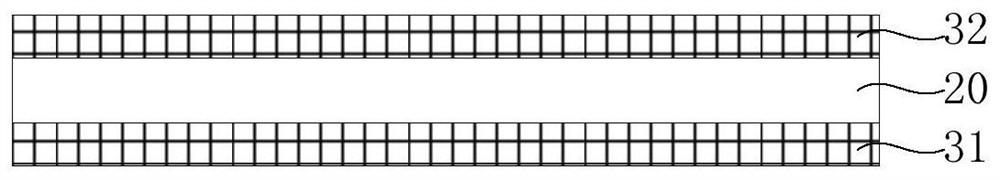
[0100] like Figure 15 As shown, in this embodiment, the housing assembly 100 includes a housing substrate 20 and two protective layers 24 . Wherein, the shell base material 20 includes a base body 21 , an adhesive layer 23 and two liquid crystal cells 22 . The matrix 21 is a composite plate of the PMMA layer 211 and the PC layer 212 , and the PMMA layer 211 has a predetermined color. Two liquid crystal units 22 are bonded to the PC layer 212 side and the PMMA layer 211 side of the substrate 21 respectively through the bonding layer 23, each liquid crystal unit 22 includes an alignment layer 222 and a liquid crystal layer 221, and the liquid crystal layer 221 is arranged on the corresponding A side of the alignment layer 222 facing the substrate 21 . The two protective layers 24 are respectively located on the sides of the two liquid crystal cells 22 away from the substrate 21 .

Embodiment 2

[0102] like Figure 16 As shown, in this embodiment, the housing assembly 100 includes a housing substrate 20 and two protective layers 24 . Wherein, the shell base material 20 includes a base body 21 , an adhesive layer 23 and two liquid crystal cells 22 . The matrix 21 is a composite plate of the PMMA layer 211 and the PC layer 212 , and the PC layer 212 has a predetermined color. Two liquid crystal units 22 are bonded to the PC layer 212 side and the PMMA layer 211 side of the substrate 21 respectively through the bonding layer 23, each liquid crystal unit 22 includes an alignment layer 222 and a liquid crystal layer 221, and the liquid crystal layer 221 is arranged on the corresponding A side of the alignment layer 222 facing the substrate 21 . The two protective layers 24 are respectively located on the sides of the two liquid crystal cells 22 away from the substrate 21 .

Embodiment 3

[0104] like Figure 17 As shown, in this embodiment, the housing assembly 100 includes a housing substrate 20 and two protective layers 24 . Wherein, the shell base material 20 includes a base body 21 , an adhesive layer 23 and two liquid crystal cells 22 . Wherein, the matrix 21 is a composite plate of the PMMA layer 211 and the PC layer 212 , and both the PMMA layer 211 and the PC layer 212 have preset colors. The two liquid crystal cells 22 are respectively bonded to the PC layer 212 side and the PMMA layer 211 side of the substrate 21 through the bonding layer 23, each liquid crystal cell 22 includes an alignment layer 222 and a liquid crystal layer 221, and the liquid crystal layer 221 is arranged on the alignment layer 222 facing the side of the base 21 . The two protective layers 24 are respectively located on the sides of the two liquid crystal cells 22 away from the substrate 21 .


PUM

PropertyMeasurementUnit
thicknessaaaaaaaaaa
thicknessaaaaaaaaaa
thicknessaaaaaaaaaa

Abstract

The invention discloses a shell assembly and a manufacturing method thereof and electronic equipment, the shell assembly comprises a shell base material, and the shell base material comprises a base body and at least one liquid crystal unit; wherein the base body has a preset color; each liquid crystal unit is arranged on one side of the base body and comprises oriented liquid crystals, so that incident light entering the liquid crystal units can be reflected out through the liquid crystals. In this way, the aesthetic feeling of the shell assembly can be enhanced, and the use requirement can be met.

Description

technical field [0001] The present application relates to the field of housing technology, in particular to a housing assembly, a manufacturing method thereof, and electronic equipment. Background technique [0002] Due to the requirements of appearance and function, many production and living tools, such as electronic equipment, household appliances, etc., have shells. With the improvement of users' requirements for the appearance of various equipment, shells with only a single function are no longer available. able to meet the growing demand. Contents of the invention [0003] The main technical problem to be solved by the present application is to provide a shell assembly, its manufacturing method, and electronic equipment, which can enhance the aesthetic feeling of the shell assembly and meet the use requirements. [0004] In order to solve the above technical problems, a technical solution adopted by the present application is to provide a casing assembly, the casing...

Claims


Application Information

Patent Timeline
Patent Type & Authority Applications(China)
IPC IPC(8): H05K5/02G02F1/1333
Inventor 金挺顺
Owner GUANGDONG OPPO MOBILE TELECOMM CORP LTD
Why Eureka
Try Eureka