Welding method of reactor core shroud assembly

A welding method and shroud technology, applied in welding equipment, welding accessories, arc welding equipment, etc., can solve the problems of high welding cost of core shrouds, achieve the effect of reducing welding costs and ensuring welding efficiency

Inactive Publication Date: 2022-04-05
DONGFANG ELECTRIC WUHAN NUCLEAR EQUIP
View PDF16 Cites 0 Cited by
  • Summary
  • Abstract
  • Description
  • Claims
  • Application Information

AI Technical Summary

Problems solved by technology

[0005] The purpose of the present invention is to overcome the above-mentioned technical deficiencies, propose a welding method for the core shroud assembly, and solve the technical problem that the welding cost of the core shroud is relatively high in the prior art

Method used


Image

  • Welding method of reactor core shroud assembly
  • Welding method of reactor core shroud assembly
  • Welding method of reactor core shroud assembly

Examples


Embodiment Construction

[0051] In order to make the object, technical solution and advantages of the present invention clearer, the present invention will be further described in detail below in conjunction with the accompanying drawings and embodiments. It should be understood that the specific embodiments described here are only used to explain the present invention, not to limit the present invention.

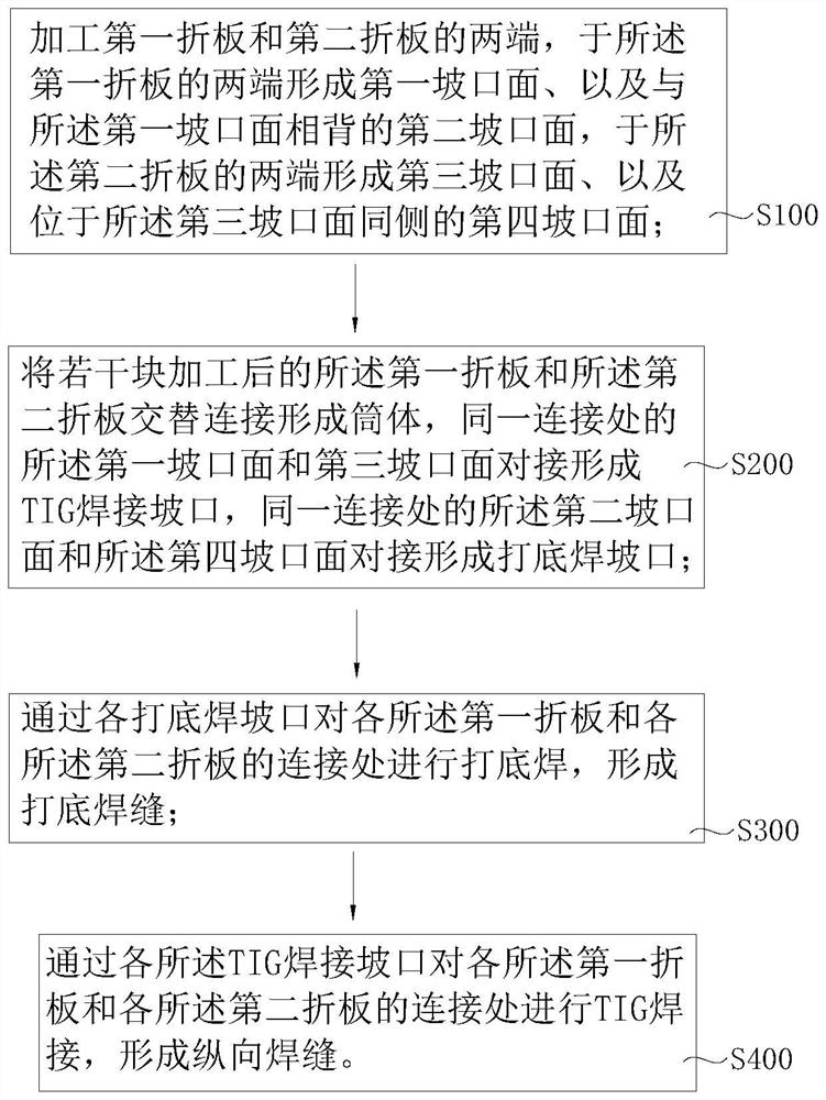
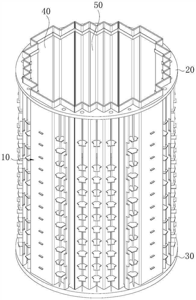
[0052] The invention provides a welding method for a core shroud assembly, such as Figure 1-12 shown, including the following steps:

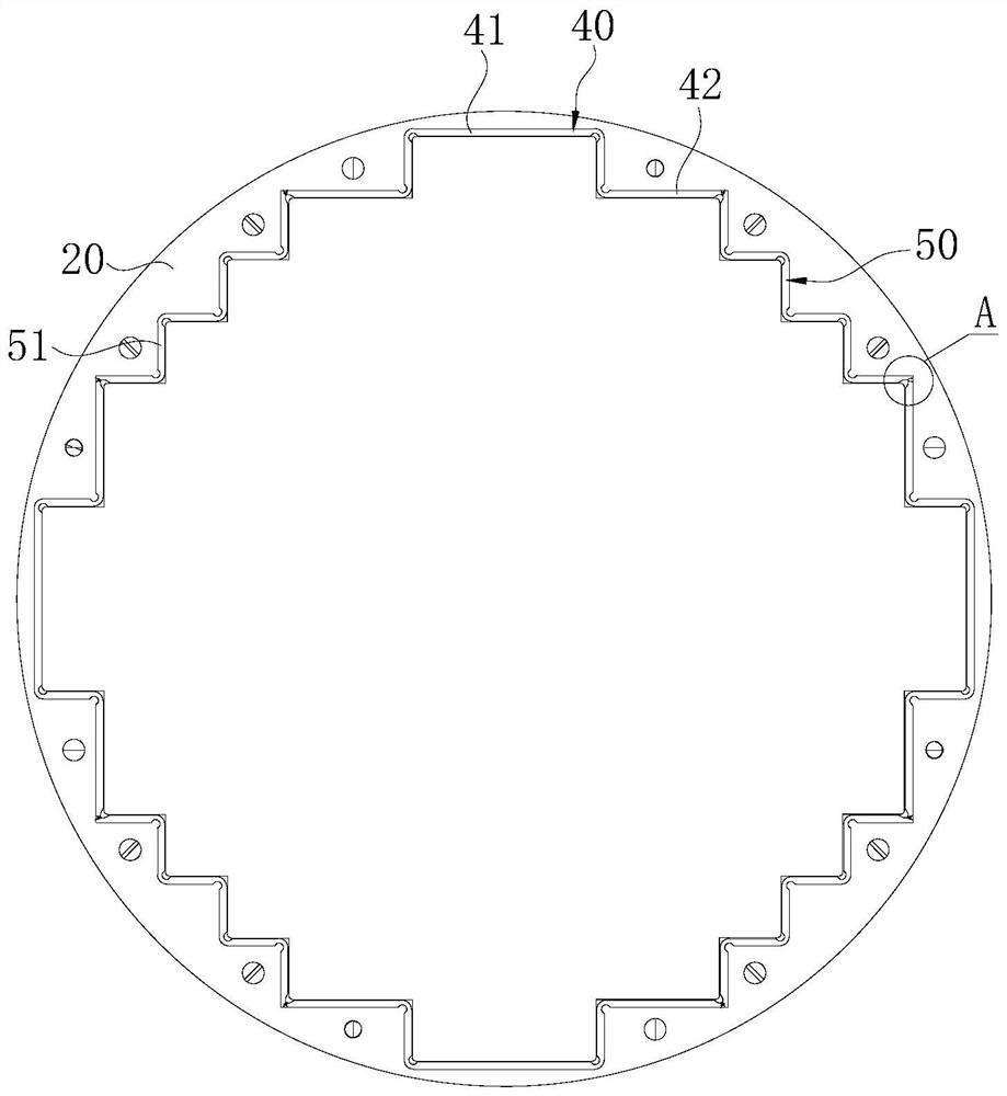
[0053] S100: Processing the first folded plate 40 and the second folded plate 50, forming a first grooved surface 43 and a second grooved surface 44 opposite to the first grooved surface 43 at both ends of the first folded plate 40, A third grooved surface 52 and a fourth grooved surface 53 located on the same side of the third grooved surface 52 are formed at both ends of the second folded plate 50;

[0054] S200: alternately arrange the processed first folded p...


PUM

PropertyMeasurementUnit
Radiusaaaaaaaaaa

Abstract

The invention relates to the technical field of welding processes, in particular to a welding method of a reactor core shroud assembly, which comprises the following steps: forming a first groove surface and a second groove surface at two ends of a first folded plate, forming a third groove surface and a fourth groove surface at two ends of a second folded plate, and alternately connecting a plurality of processed first folded plates and second folded plates to form a barrel; due to the fact that the second groove face and the fourth groove face at the same connecting position are in butt joint to form the backing welding groove, the first groove face and the third groove face are in butt joint to form the TIG welding groove, the backing welding groove can be used for backing welding of the first folded plate and the second folded plate, and the premise is provided for the first folded plate and the second folded plate to achieve stability and meet the welding precision requirement through TIG welding. By means of TIG welding of the longitudinal weld joints, automatic welding of the longitudinal weld joints of the reactor core shroud assembly can be achieved, the welding efficiency is guaranteed, and meanwhile the welding cost of the reactor core shroud assembly can be effectively reduced.

Description

technical field [0001] The invention relates to the technical field of welding technology, in particular to a welding method for a core shroud assembly. Background technique [0002] The core shroud is located in the basket assembly and on the core support plate. This assembly constitutes the radial periphery of the core and provides a guide flow path for the reactor coolant as it passes through the core by controlling the size of the chamber (ie, controlling the gap between the fuel assembly and the core shroud). The core shroud can limit the radial flow velocity or injection velocity of the coolant entering the core, and the core shroud allows the coolant (ie bypass flow) to flow through the cavity between the basket and the outer wall of the core shroud. [0003] The core shroud mainly includes a cylinder, a top plate and a bottom plate. The bottom plate and the top plate are located at both ends of the cylinder, and two annular seams are formed between the top plate and...

Claims


Application Information

Patent Timeline
IPC IPC(8): B23K9/167B23K9/32
Inventor 唐炼王永佳董明亮杜凡刘杨舒华安
Owner DONGFANG ELECTRIC WUHAN NUCLEAR EQUIP
Why Eureka
Try Eureka