
Film hole grid modification method

A technology of air film holes and grids, applied in geometric CAD, design optimization/simulation, etc., can solve the problems of wasting manpower and time resources, limiting the speed of optimization iterations, etc., to reduce iteration cycles, reduce manpower dependence, reduce effect of complexity

Pending Publication Date: 2022-04-05
BEIHANG UNIV
View PDF0 Cites 0 Cited by
  • Summary
  • Abstract
  • Description
  • Claims
  • Application Information

AI Technical Summary

Problems solved by technology

[0006] In order to solve the problems of wasting manpower and time resources and limiting the speed of optimization iterations in the existing grid modification method, the present invention provides a gas film hole grid modification method

Method used


Image

  • Film hole grid modification method
  • Film hole grid modification method
  • Film hole grid modification method

Examples


Embodiment Construction

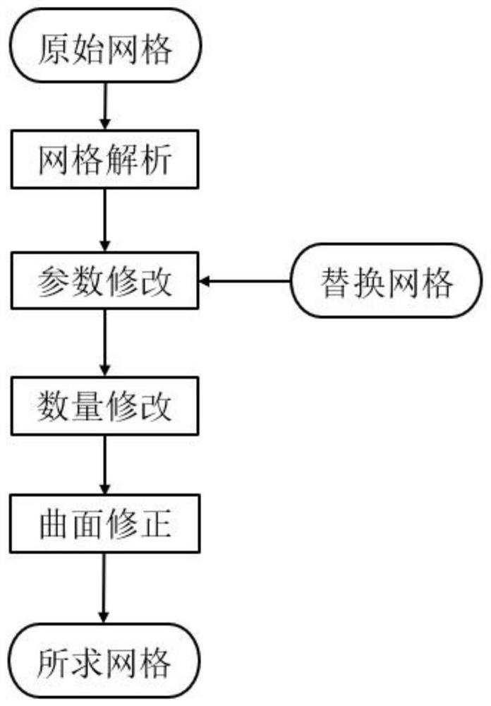
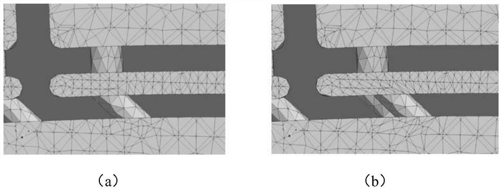
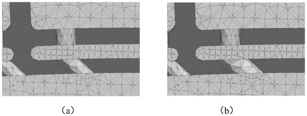
[0021] combine Figure 1 to Figure 5 Describe this embodiment, a method for modifying the grid of gas film holes. The method uses four modules: grid analysis module, parameter modification module, quantity modification module and surface correction module to perform grid analysis, parameter modification, quantity modification and surface modification respectively. Correction; the specific process is as follows:

[0022] 1. Grid analysis: read the existing grid file, and obtain the characteristic parameters of the target gas film hole and the surrounding grid point information through algorithm analysis through the position information of the target gas film hole.

[0023] The position information that needs to be input in this step consists of two parameters, the coordinates of the center of the sphere and the radius of the sphere. It is required that there are only target air film holes within the sphere.

[0024] The grid is composed of surfaces, the surface is composed of ...


PUM


Abstract

The invention discloses a film hole grid modification method, relates to the technical field of computational fluid dynamics application, solves the problems that manpower and time resources are wasted and the speed of optimization iteration is limited in an existing grid modification method, and is realized by a grid analysis module, a parameter modification module, a quantity modification module and a curved surface modification module. The grid analysis module reads the existing grid file, analyzes the position information of the target gas film hole, and obtains the parameters of the target gas film hole and the information of surrounding grid points; the parameter modification module modifies the aperture, the inclination angle and the position so as to modify the parameters of the film hole; a number modification module is adopted to modify the number of the target gas film holes after parameter modification, and deletion and increase of the gas film holes are achieved; and the curved surface correction module corrects the grid points near the target gas film hole according to the coordinates of the points of the wall surface near the gas film hole and the fitting, so that the shape of the wall surface near the modified gas film hole is not changed. The complexity of the method is reduced, and the universality of the method is improved.

Description

technical field [0001] The invention relates to the technical field of computational fluid dynamics applications, in particular to a method for modifying a gas film hole grid. Background technique [0002] Computational Fluid Dynamics (CFD) is based on fluid mechanics and computer science. It starts from the calculation method and uses the fast calculation ability of the computer to obtain the approximate solution of the fluid control equation. technical means. [0003] Since problems in actual engineering usually cannot be analyzed and solved, and the cost of making models for experiments is high, CFD is usually relied heavily on in the process of product design for numerical simulation. The CFD calculation process includes grid generation, numerical calculation and result processing, among which Mesh generation takes up most of the human resources and directly determines the degree of automation of design iterations. Therefore, how to improve the mesh generation speed of...

Claims


Application Information

Patent Timeline
IPC IPC(8): G06F30/28G06F30/17
Inventor 朱剑琴解广源陶智邱璐李地科黄俊杰
Owner BEIHANG UNIV
Learn More