
Method for correcting transverse chromatic aberration of image

A technology of lateral chromatic aberration and image correction, which is applied in the field of image processing, can solve problems such as slow calculation speed, low correction efficiency, and large amount of computation for cubic polynomial correction, and achieve fast correction speed, high correction efficiency, and fast calculation speed.

Pending Publication Date: 2022-04-05
BEIJING LUSTER LIGHTTECH +1
View PDF0 Cites 0 Cited by
  • Summary
  • Abstract
  • Description
  • Claims
  • Application Information

AI Technical Summary

Problems solved by technology

[0005] This application provides a method for correcting the lateral chromatic aberration of an image to solve the problem in the prior art that the correction of the cubic polynomial requires a large amount of computation, especially the slow calculation speed when correcting the lateral chromatic aberration of an image with a large image resolution. , the problem of low correction efficiency

Method used


Image

  • Method for correcting transverse chromatic aberration of image
  • Method for correcting transverse chromatic aberration of image
  • Method for correcting transverse chromatic aberration of image

Examples


Embodiment 1

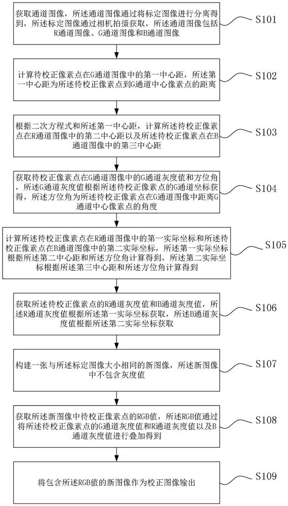
[0060] Such as figure 2 As shown, Embodiment 1 provides a method for correcting lateral chromatic aberration of an image, the method comprising:

[0061] S101. Acquire a channel image, the channel image is obtained by separating a calibration image, the calibration image is captured by a camera, and the channel image includes an R channel image, a G channel image, and a B channel image;

[0062] S102. Calculate the first center distance of the pixel to be corrected in the G channel image, where the first center distance is the distance from the pixel to be corrected to the central pixel of the G channel;

[0063] S103. Calculate a second center distance of the pixels to be corrected in the R channel image and a third center distance of the pixels to be corrected in the B channel image according to the quadratic equation and the first center distance;

[0064] S104. Obtain the G channel gray value and azimuth angle of the pixel to be corrected in the G channel image, the G ch...

Embodiment 2

[0100] The present application provides a terminal device, including a memory, a processor, and a computer program stored in the memory and operable on the processor. When the processor executes the computer program, one of the steps in Embodiment 1 is implemented. Steps in a method of correcting lateral chromatic aberration of an image.

Embodiment 3

[0102] The present application provides a computer-readable storage medium, the computer-readable storage medium stores a computer program, and when the computer program is executed by a processor, the steps of a method for correcting lateral chromatic aberration of an image in Embodiment 1 are realized.


PUM


Abstract

The invention provides a method for correcting transverse chromatic aberration of an image. The method comprises the following steps: calculating a first center distance of to-be-corrected pixel points in a G-channel image; constructing a quadratic equation of the second center distance and the first center distance in the R channel image and a quadratic equation of the third center distance and the first center distance in the B channel image; calculating and acquiring an R channel gray value and a B channel gray value of the to-be-corrected pixel point according to the quadratic equation in combination with other corresponding parameters of the G channel image, the R channel image and the B channel image; and superposing the G channel gray value, the R channel gray value and the B channel gray value to serve as an RGB value of a to-be-corrected pixel point in the new image and outputting the RGB value. When transverse chromatic aberration correction is carried out on the calibration image, the transverse axis and the longitudinal axis only need to fit one quadratic equation, and compared with an existing scheme that the transverse axis and the longitudinal axis need to be subjected to cubic polynomial correction in a fitting mode, the calculation amount is smaller, the transverse chromatic aberration correction speed of the calibration image is higher, and the correction error is smaller.

Description

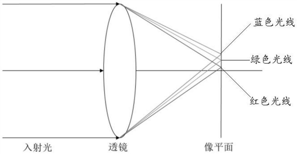
technical field [0001] The present application relates to the technical field of image processing, and in particular to a method for correcting lateral chromatic aberration of an image. Background technique [0002] In the image processing system, when visible light passes through the lens of the camera lens, since the refractive index of the refraction medium changes with the wavelength, different colors of light have different wavelengths, and the longer the wavelength, the greater the refractive index. Therefore, light rays of different wavelengths will focus on different positions of the image plane after being imaged by the lens. This phenomenon is called lateral chromatic aberration. The lateral chromatic aberration is mainly caused by the lens. When the lateral chromatic aberration is serious, the image of the object captured by the camera will have colored edges. figure 1 Generate a schematic for lateral chromatic aberration, from figure 1 It can be seen from the f...

Claims


Application Information

Patent Timeline
Patent Type & Authority Applications(China)
IPC IPC(8): G06T5/00G06T7/90
Inventor 崔茗宇郭慧戚涛张见姚毅杨艺
Owner BEIJING LUSTER LIGHTTECH
Learn More