
Zone area energy control system

An energy control system, a technology in the Taiwan area, applied in information technology support systems, power network operating system integration, sustainable buildings, etc. The effect of reducing comprehensive energy consumption, realizing sustainable utilization and improving consumption capacity

Pending Publication Date: 2022-04-05
NANJING NARI GROUP CORP +3
View PDF0 Cites 0 Cited by
  • Summary
  • Abstract
  • Description
  • Claims
  • Application Information

AI Technical Summary

Problems solved by technology

On the one hand, more and more new energy sources such as photovoltaics and wind power and energy storage are connected; on the other hand, smart electrical equipment such as energy-consuming equipment in the Taiwan area, distributed new energy, orderly charging of electric vehicles, and smart home energy-using services There are more and more smart home appliances, and the energy consumption is increasing; whether it is the access of new energy sources such as photovoltaics and wind power and energy storage, or the access of a large number of energy-consuming equipment such as smart electrical equipment and smart home appliances, it will affect the stability of the power grid. The operation caused a certain impact, and at the same time, due to the uncoordinated energy requirements of the production capacity, energy storage equipment and energy consumption equipment, it led to unreasonable allocation and waste of energy

Method used


Image

  • Zone area energy control system
  • Zone area energy control system
  • Zone area energy control system

Examples


Embodiment Construction

[0042] The present invention will be further described below in conjunction with the accompanying drawings. The following examples are only used to illustrate the technical solution of the present invention more clearly, but not to limit the protection scope of the present invention.

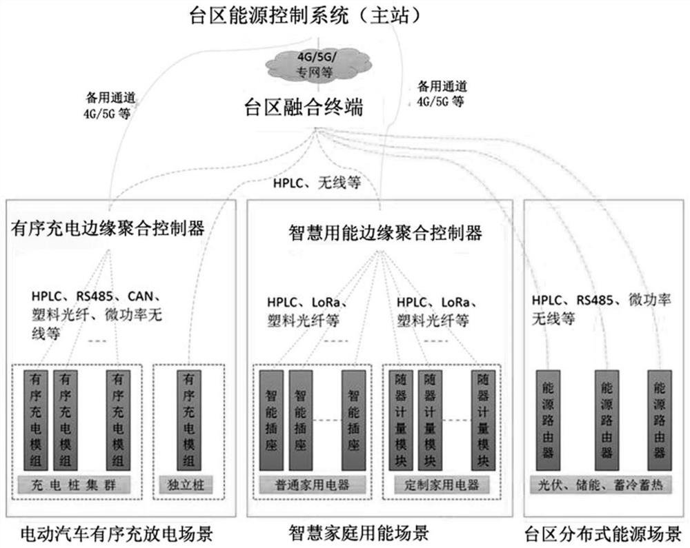
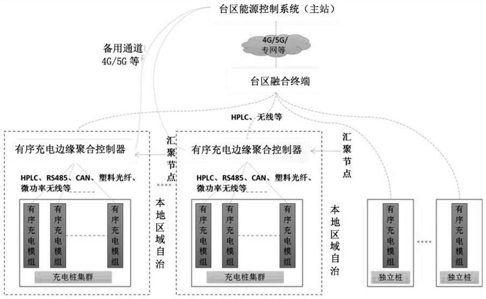
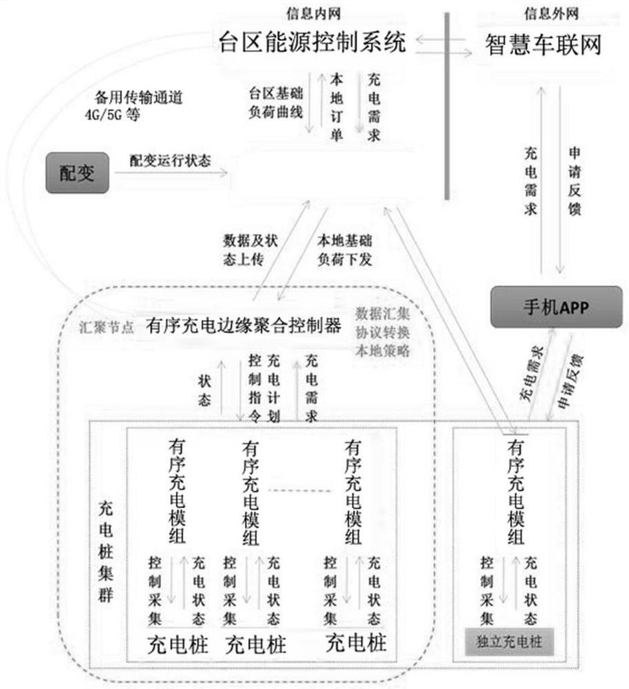
[0043] A station area energy control system, including a main station, a station area fusion terminal, an electric vehicle orderly charging and discharging unit, a smart home energy unit, and a station area distributed energy unit; the main station is connected to the station area fusion terminal through communication; The station-area fusion terminal is respectively connected to the orderly charging and discharging unit of the electric vehicle, the smart home energy-consuming unit and the station-area distributed energy unit.

[0044] The key equipment of the energy control system in the station area is mainly concentrated in the system perception layer. The optimization of energy control in T...


PUM


Abstract

The invention discloses a transformer area energy control system in the technical field of electric power automation control. The transformer area energy control system comprises a master station, a transformer area fusion terminal, an electric vehicle ordered charging and discharging unit, a smart home energy consumption unit and a transformer area distributed energy unit. The main station is in communication connection with the transformer area fusion terminal; the transformer area fusion terminal is in communication connection with the electric vehicle ordered charging and discharging unit, the smart home energy consumption unit and the transformer area distributed energy unit. According to the invention, reasonable distribution and application of energy are realized, and the stability of a power grid is improved; in the aspect of economic benefits, comprehensive energy consumption of resident users is reduced; and in the aspect of social benefits, energy conservation and emission reduction are met, the energy utilization efficiency is improved, development of clean energy on the user side is promoted, the proportion of electric energy in terminal energy consumption is increased, and sustainable utilization of energy is achieved.

Description

technical field [0001] The invention belongs to the technical field of electric power automation control, and in particular relates to a station area energy control system. Background technique [0002] With the acceleration of energy technology and digital innovation, the traditional energy industry value chain is being reshaped, and a new energy ecosystem is being formed. On the one hand, more and more new energy sources such as photovoltaics and wind power and energy storage are connected; on the other hand, smart electrical equipment such as energy-consuming equipment in the Taiwan area, distributed new energy, orderly charging of electric vehicles, and smart home energy-using services There are more and more smart home appliances, and the energy consumption is increasing; whether it is the access of new energy sources such as photovoltaics and wind power and energy storage, or the access of a large number of energy-consuming equipment such as smart electrical equipment ...

Claims


Application Information

Patent Timeline
IPC IPC(8): H02J13/00H02J3/24H02J3/38H02J3/32H02J3/18H02J3/14H02J3/26H02H7/26
CPCY02E40/30Y02E40/50Y02B70/30Y02B70/3225Y02B90/20Y04S20/12Y04S20/222Y04S20/242
Inventor 黄月昊张浩赵翔蔡华周斌成海生张建伟岳鹏陈诚盛昕炜张高山刘永春曹冬华王瑞
Owner NANJING NARI GROUP CORP
Learn More