Temperature controller for micro motor

A technology for temperature controllers and micro motors, applied in the direction of casing/cover/support, cooling/ventilation devices, electrical components, etc. Problems such as the use effect of the motor, to achieve the effect of easy replacement and maintenance, increased difficulty, and improved practicability

Active Publication Date: 2022-04-05
SUZHOU IND PARK KAIN ELECTRONICS SCI & TECH CO LTD
View PDF12 Cites 0 Cited by
  • Summary
  • Abstract
  • Description
  • Claims
  • Application Information

AI Technical Summary

Problems solved by technology

[0005]In order to make up for the deficiencies of the existing technology, due to the small size of the micro-motor, setting a temperature controller inside the motor not only increases the difficulty of assembly and processing of the motor, but also The problem that the temperature controller is not easy to replace and repair after damage occurs, thereby affecting the use effect of the micro motor, the invention provides a temperature controller for a micro motor

Method used


Image

  • Temperature controller for micro motor
  • Temperature controller for micro motor
  • Temperature controller for micro motor

Examples


Embodiment 1

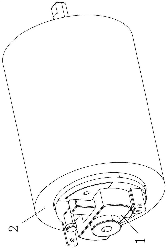
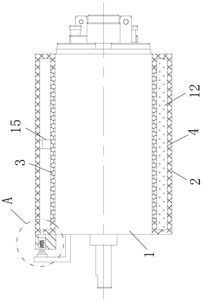
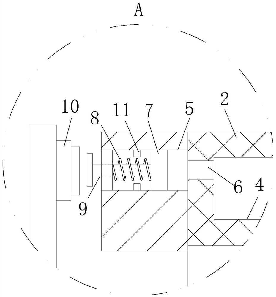
[0029] see Figure 1-5 As shown, a temperature controller for a micro motor according to the present invention includes a motor body 1; A heat conduction layer 3 is provided on the side wall of the protective cover 2, a cavity 4 is opened inside the protective cover 2, a sliding cavity 5 is connected to one end of the protective cover 2, and a sliding cavity 5 is connected to the end of the protective cover 2, which is connected to the inner end of the sliding cavity 5. The airflow hole 6 through which the slide chamber 5 is slidably connected to the slide block 7, the side wall of the slide block 7 fits the inner wall of the slide chamber 5, and the gap between the slide block 7 and the end of the slide chamber 5 An elastic member 8 is connected, and the end of the slider 7 away from the airflow hole 6 is connected with a push rod 9, and the motor body 1 corresponding to one side of the push rod 9 is connected with a touch switch capable of controlling the operation of the mo...

Embodiment 2

[0038] see Figure 6 As shown, the inside of the slide bar 21 is provided with an oil storage chamber 25, the bottom end of the oil storage chamber 25 is slidably connected with a pressure block 26, and there is an elastic connection between the pressure block 26 and the bottom end of the oil storage chamber 25. body 27, a group of oil outlet holes 28 are provided at the position where the top of the sliding rod 21 corresponds to the side wall of the impact block 17, and a lubrication groove is provided at the position where the top of the expansion block 20 fits with the sliding rod 21, so The inside of the lubricating groove is connected with a support pipe 29, and the end of the support pipe 29 close to the slide bar 21 is filled with an absorbing block 30 of water-absorbing material; during operation, lubricating oil is pressed into the oil storage chamber 25 in advance, and when the expansion block 20 The top pushes the impact block 17 on the slide bar 21 to move upward u...


PUM


Abstract

The invention relates to the technical field of controllers, in particular to a temperature controller for a micro motor, which comprises a motor body, the side wall of the motor body is sleeved with a protective sleeve, a cavity is formed in the protective sleeve, one end of the protective sleeve is connected with a sliding cavity, an airflow hole communicated with the inner end of the sliding cavity is formed in the end of the protective sleeve, a sliding block is slidably connected into the sliding cavity, and an elastic piece is connected between the sliding block and the end of the sliding cavity. The end, away from the airflow hole, of the sliding block is connected with a push rod, and the motor body is connected with a point contact switch. The situation that the motor is burnt out due to the fact that the continuous working temperature is too high can be reduced, the temperature control structure is installed outside the motor body, the difficulty of assembling and machining of the motor is improved, meanwhile, the temperature control structure is easy to replace and maintain after being damaged, the situation that the motor is accidentally damaged in the disassembling process is reduced, and the service life of the motor is prolonged. And the practicability of the motor is greatly improved.

Description

technical field [0001] The invention relates to the technical field of controllers, in particular to a temperature controller for a micro motor. Background technique [0002] The thermostat is a series of automatic control elements that cause physical deformation inside the switch according to the temperature change of the working environment, resulting in some special effects, and a series of automatic control elements that produce conduction or disconnection actions, or electronic components at different temperatures. Different principles are used to provide temperature data to the circuit for the circuit to collect temperature data. When some existing motors are in use, in order to prevent the motor from burning out due to continuous working temperature, a temperature sensor is usually installed inside the motor. [0003] However, due to the small size of the micro motor, installing a temperature controller inside the motor not only increases the difficulty of assembly an...

Claims


Application Information

Patent Timeline
Patent Type & Authority Applications(China)
IPC IPC(8): H02K5/18H02K11/25H02K9/19H02K9/20
Inventor 庞栋梁
Owner SUZHOU IND PARK KAIN ELECTRONICS SCI & TECH CO LTD
Why Eureka
Try Eureka