Circulating ventilation automobile transom window

A technology for automobiles and roof windows, which is applied to vehicle parts, air handling equipment, heating/cooling equipment, etc. It can solve the problems of speeding up air circulation, poor air, and ventilation effects that cannot achieve ventilation effects, so as to improve the effect of air circulation , Improve the effect of poor air quality

Pending Publication Date: 2022-04-08
罗萍
View PDF0 Cites 0 Cited by
  • Summary
  • Abstract
  • Description
  • Claims
  • Application Information

AI Technical Summary

Problems solved by technology

[0002] As everyone knows, the interior environment of a car is relatively closed, so it is necessary to ventilate the car to improve ride comfort. For this reason, existing cars are equipped with necessary roof windows, while existing conventional roof windows usually have It includes the inner shell and the outer shell hinged on the roof and covering the inner shell. When the interior of the car needs to be ventilated, the window formed by opening the outer shell can circulate the air inside and outside. Of course, In order to ensure the air circulation in the car, a circulation fan can also be installed at the bottom of the car interior shell, and an air inlet and an air outlet are arranged on the car interior shell, so that when the car shell is closed, the circulation fan can be used to The air in the car can be circulated by using the air inlet and the air outlet, which improves the purpose of the air flow in the car. The existing structure mainly has the following problems. On the one hand, when the air needs to be circulated externally, due to the The air pressure is basically balanced. It is difficult for the air outside the car to enter the car. In fact, it can only have a limited ventilation effect but not a ventilation effect. It cannot solve the problem of poor air in the car. On the other hand, The circulating fan installed on the top of the car shell only serves to accelerate the air circulation, and the air environment problem in the car cannot be substantially solved.

Method used


Image

  • Circulating ventilation automobile transom window
  • Circulating ventilation automobile transom window
  • Circulating ventilation automobile transom window

Examples


Embodiment 1

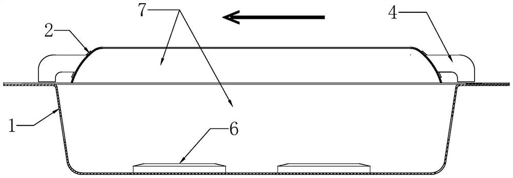
[0018] Such as figure 1 As shown, the roof window of the circulating ventilation vehicle in this embodiment includes the interior shell 1 and the exterior shell 2 installed on the top of the interior shell. The interior shell 1 and the exterior shell 2 are mounted together to form a ventilation cavity 7, outer circulation openings 3 are respectively arranged on the front and rear side walls of the vehicle body shell 2 and a ventilation pipe 4 is installed on the two outer circulation openings 3, as can be seen from the figure, two ventilation pipes 4 are installed on the On the front and rear side walls of the car shell body 2 and the opening is downward, the filter material that filters the air can be filled in the two ventilation pipes 4 simultaneously, and said filter material is preferably a filter screen, here also activated carbon, hepa, etc. The effect of filtering air is played by the filter material, and the filled filter material can be replaced. When replacing the f...

Embodiment 2

[0021] Such as figure 1 As shown, the roof window of the circulating ventilation vehicle in this embodiment includes the interior shell 1 and the exterior shell 2 installed on the top of the interior shell. The interior shell 1 and the exterior shell 2 are mounted together to form a ventilation Cavity 7, outer circulation openings 3 are arranged on the left and right side walls of the vehicle shell body 2 respectively and a ventilation pipe 4 is installed on the two external circulation openings 3, as can be seen from the figure, the ventilation pipe 4 is installed on the vehicle casing through the mounting plate The left and right side walls of the body 2 (the front and rear directions shown in the figure are defined as the front side and the rear side, and the directions perpendicular to the front and rear directions shown in the figure are positioned as the left and right sides on the same horizontal plane) and the opening is downward. The left and right side walls of the i...

Embodiment 3

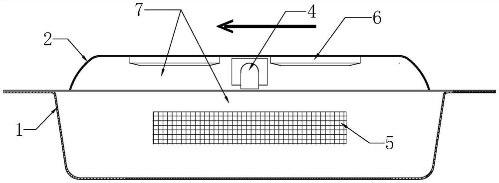
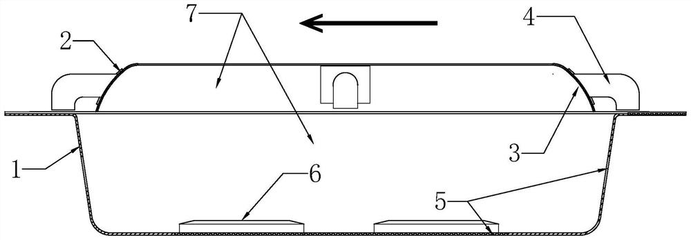
[0023] Such as image 3 As shown, the roof window of the circulating ventilation vehicle in this embodiment is roughly the same as that of Embodiment 1, the difference is that a square inner circulation opening 5 is arranged on the bottom of the interior housing 1 on which a piece of air is installed. In a square mesh plate, two circulation fans 6 are installed above the internal circulation opening 5, and at the same time, an external circulation opening 3 equipped with a ventilation pipe 4 is respectively arranged on the front, rear, left, and right side walls of the car shell body 2, Change its ventilation effect.


PUM


Abstract

The invention discloses a circular ventilation automobile transom window. Comprising a vehicle inner shell and a vehicle outer shell installed on the top of the inner shell, at least one outer circulation opening is formed in the vehicle outer shell, at least one inner circulation opening is formed in the vehicle inner shell, a ventilation cavity is formed after the vehicle inner shell and the vehicle outer shell are installed in an involution mode, and at least one circulation fan is arranged in the ventilation cavity. Through the circulating fan, external air can enter the automobile through the ventilation cavity, and air in the automobile can be exhausted out of the automobile through the ventilation cavity. The air circulation device has the advantages that air in the automobile can be exhausted out of the automobile through the circulating fan, air outside the automobile can be led into the automobile through the circulating fan to achieve the fresh air leading-in function, and therefore the requirement for external air exchange is met, the purpose of improving the air circulation effect is achieved, and the problem that the quality of air in the automobile is poor is greatly solved.

Description

technical field [0001] The invention relates to a car roof window structure, in particular to a car roof window with circulation ventilation. Background technique [0002] As everyone knows, the interior environment of a car is relatively closed, so it is necessary to ventilate the car to improve ride comfort. For this reason, existing cars are equipped with necessary roof windows, while existing conventional roof windows usually have It includes the inner shell and the outer shell that is hinged on the roof and covers the inner shell. When the interior of the car needs to be ventilated, the window formed by opening the outer shell can circulate the inside and outside air. Of course, In order to ensure the air circulation in the car, a circulating fan can also be installed at the bottom of the car's inner shell, and an air inlet and an air outlet are arranged on the car's inner shell, so that when the car's outer shell is closed, the circulating fan can be used to The air i...

Claims


Application Information

Patent Timeline
Patent Type & Authority Applications(China)
IPC IPC(8): B60H1/24B60H3/06
Inventor 罗萍
Owner 罗萍
Why Eureka
Try Eureka