
Vertical falling locking mechanism for rail transportation

A locking mechanism and rail transportation technology, applied in the field of rail transportation, can solve the problems of high-speed falling, large impact force, stall of transport load-bearing boxes, etc., and achieve the effects of increasing the contact area, increasing the friction force, and reducing the falling speed

Pending Publication Date: 2022-04-08
王明洪
View PDF0 Cites 1 Cited by
  • Summary
  • Abstract
  • Description
  • Claims
  • Application Information

AI Technical Summary

Problems solved by technology

[0005] The purpose of the present invention is to provide a vertical fall locking mechanism for rail transportation, to solve the problems in the vertical rail transportation mentioned in the above background technology that long-term operation will cause mechanical aging and other problems. Once a failure occurs, it will cause the transportation load The box stalls, causing it to fall at high speed. There is no emergency deceleration locking structure, which will cause serious shocks to people or objects inside the load-bearing box, causing serious injuries, and there is a very high potential safety hazard. In an instant, a large impact force will be generated, which will easily cause damage to the load-bearing box and cause economic losses.

Method used


Image

  • Vertical falling locking mechanism for rail transportation
  • Vertical falling locking mechanism for rail transportation
  • Vertical falling locking mechanism for rail transportation

Examples


Embodiment

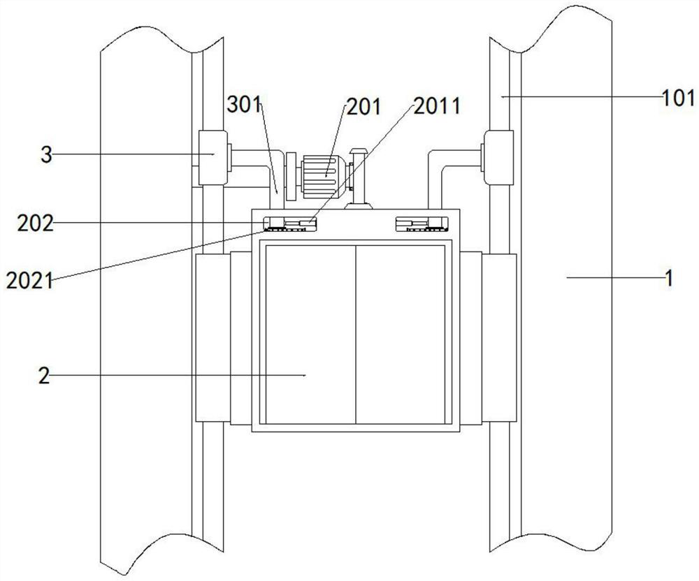
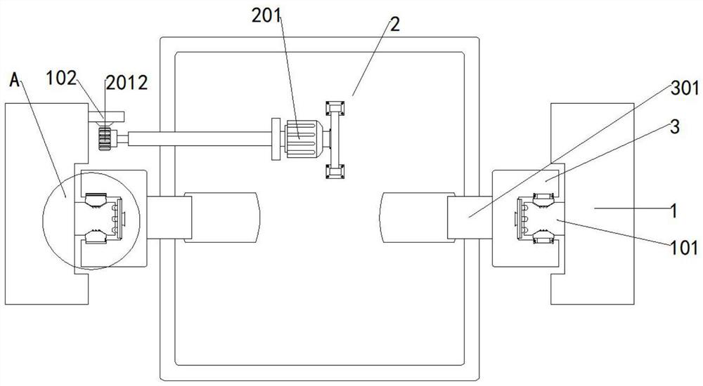
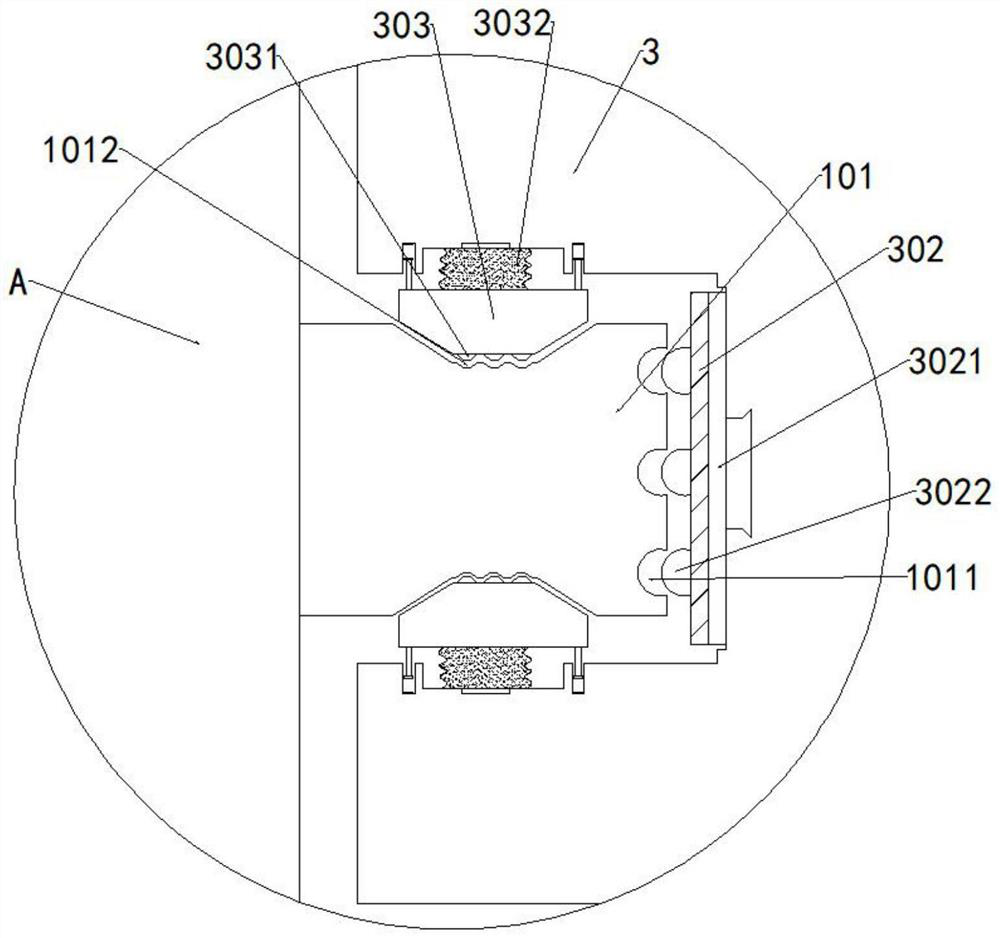
[0026] as attached figure 1 to attach Figure 5 Shown:

[0027] The present invention provides a vertical fall locking mechanism for rail transportation. The vertical fall locking mechanism for rail transportation includes a load-bearing wall 1, a track 101 and a load-bearing box 2. The number of load-bearing walls 1 is two and symmetrical to each other. 1. Rails 101 are fixedly installed on opposite sides, and load-bearing boxes 2 are slidably connected between the rails 101, and a stall locking mechanism is arranged above the load-bearing boxes 2.

[0028] Wherein, the stall locking mechanism includes a rack 102, a generator 201, an electric telescopic rod 2011, a gear 2012, a groove 202, a sliding rail 2021, a locking clip 3 and a connecting rod 301;

[0029] A generator 201 is rotatably connected above the load-bearing box 2, a gear 2012 is fixedly installed at the shaft joint of the generator 201, a rack 102 is fixedly installed on one side of the load-bearing wall 1, a...


PUM


Abstract

The invention provides a vertical falling locking mechanism for rail transportation, which comprises two bearing walls, rails and a bearing box, the two bearing walls are symmetrical to each other, the rails are fixedly mounted on the opposite sides of the bearing walls, the bearing box is slidably connected between the rails, a stall locking mechanism is arranged above the bearing box, and the stall locking mechanism is arranged above the bearing box. The stall locking mechanism comprises a rack, a generator, an electric telescopic rod, a gear, a groove, a sliding rail, a locking clamp and a connecting rod, the generator is rotationally connected to the upper portion of the bearing box, the gear is fixedly installed at the coupling position of the generator, and the rack is fixedly installed on one side of the bearing wall. By arranging the stall locking mechanism, at the moment of stall of the bearing box, the rotating speed of the gear is changed, the rotating speed of the generator is linked to be changed, then the current generated by power generation of the generator is increased, the electric telescopic rod is triggered to extend, the locking clamp is pushed to the track, and the bearing box is rapidly decelerated till being locked.

Description

technical field [0001] The invention relates to the technical field of rail transportation, in particular to a vertical fall locking mechanism for rail transportation. Background technique [0002] Track refers to the route paved with strip steel for trains, trams, etc., and it can also be the route of celestial bodies running in the universe, also called track. The route of object movement refers more to certain rules, such as The movement of electrons in atoms and the movement of artificial satellites all have certain orbits. [0003] In vertical rail transportation, long-term operation will cause problems such as mechanical aging. Once a failure occurs, the transport load-bearing box will stall and cause it to fall at a high speed. There is no emergency deceleration locking structure, which will seriously damage the personnel or objects inside the load-bearing box. The vibration caused serious injury, and there is a very high potential safety hazard, and the moment the l...

Claims


Application Information

Patent Timeline
IPC IPC(8): B66B5/18B66B5/26B66B5/04
Inventor 王明洪
Owner 王明洪
Learn More