Shell mounting structure of industrial control all-in-one machine
A technology of installation structure and all-in-one machine, applied in the direction of digital processing power distribution, etc., can solve the problems of high update iteration cost, affecting the design of alarm display interface, and increasing production cost.
- Summary
- Abstract
- Description
- Claims
- Application Information
AI Technical Summary
Problems solved by technology
Method used
Image
Examples
Embodiment 1
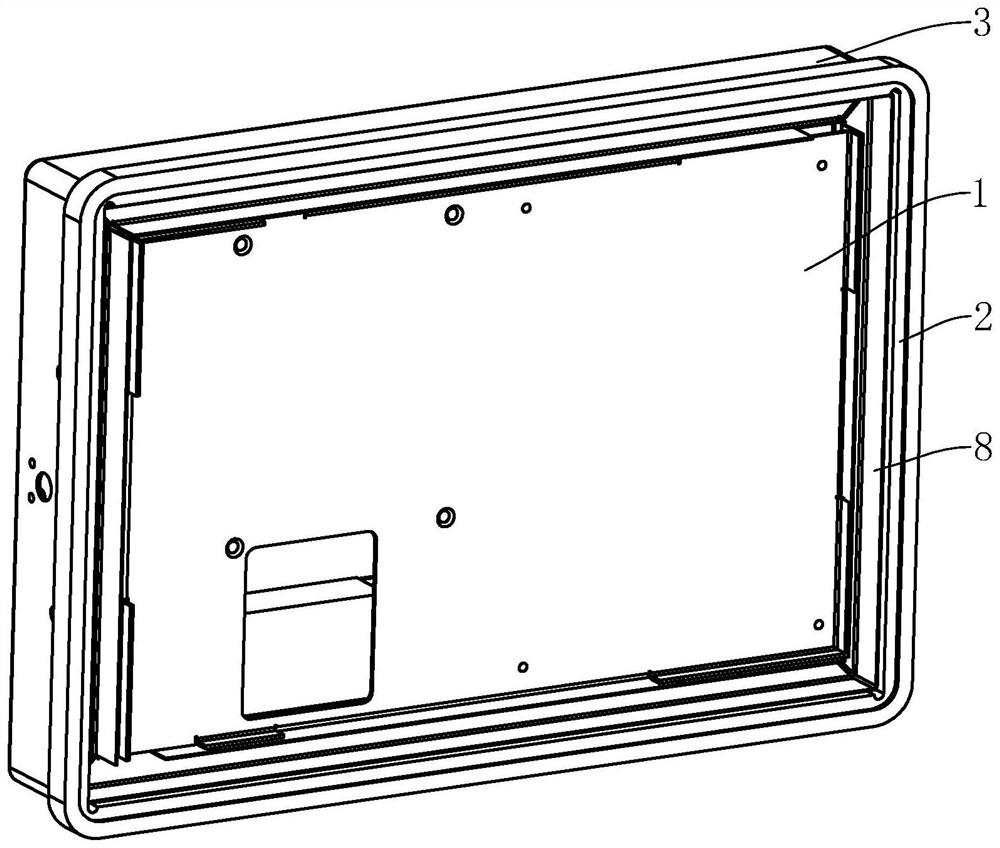
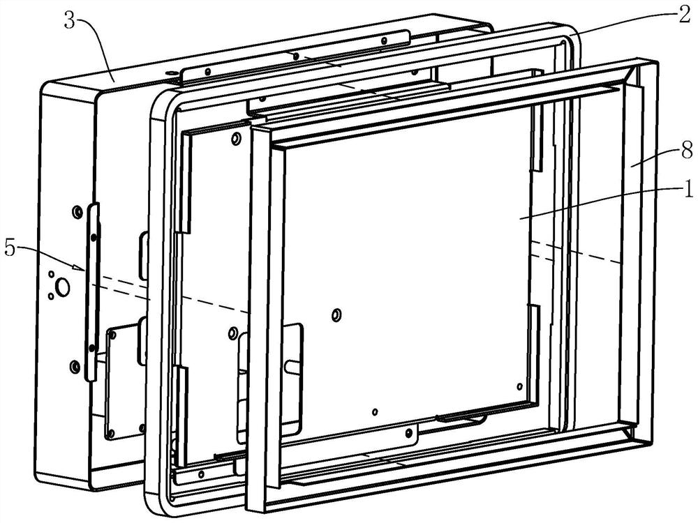
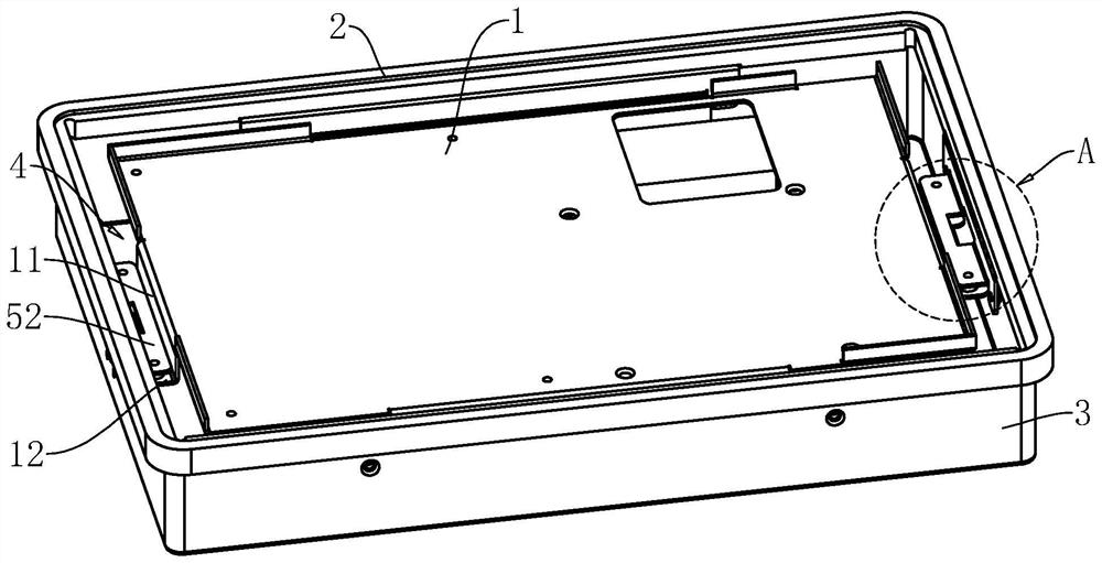
[0044] refer to figure 1 and figure 2, the present application provides a shell installation structure of an industrial computer, including a mounting plate 1 for mounting a circuit board and a rear cover 3 with one end open, and the rear cover 3 covers one side surface of the mounting plate 1 for Each electronic component on the circuit board is covered, and the front panel 2 for fixing the display screen is arranged on the end surface of the open end of the back cover 3. A window for display screen installation is reserved on the front panel 2 and the front panel 2 is ringed on the mounting plate 1. around, the front panel 2 is provided with a rectangular ring groove for the surrounding of the display screen to be embedded; wherein, the cross-sectional area of the mounting plate 1 is smaller than the inner ring area of the front panel 2, and the surrounding area of the mounting plate 1 and the inner ring of the front panel 2 A rectangular annular light groove 8 for e...
Embodiment 2
[0054] refer to Figure 8 After the second support plate 52 is fixed on the front panel 2 and the installation ear plate 55 needs to be bolted on the rear cover 3, there is often a gap for the screw to pass through the installation ear plate 55 due to positional accuracy errors. The through hole cannot be aligned with the through hole on the back cover 3 for the screw to pass through, that is, a dislocation along the depth direction of the back cover 3 occurs between the through hole on the mounting ear plate 55 and the through hole on the back cover 3; The difference between the embodiment and the first embodiment is that the side of the fixing plate 54 close to the end face of the back cover 3 fixes the elastic backing plate 7, and the elastic backing plate 7 can be compressed between the fixing plate 54 and the end face of the back cover 3, so that when the back cover 3 and the front panel 2, the deep position of the installation lug 55 inside the rear cover 3 can be adjust...
Embodiment 3
[0058] refer to Figure 9 , the difference between this embodiment and Embodiment 1 is that the supporting plate group is different. In this embodiment, the supporting plate group includes a third supporting plate arranged between the first limiting plate 11 and the second limiting plate 51 13. The first limiting plate 11, the third supporting plate 13, the second limiting plate 51 and the fixing plate 54 are integrally formed, and directly surround the installation groove 4 for the lamp groove 8 to be embedded; although there is no embodiment The standardized manufacturing of the fixed part 5 in Yizhong has the advantage of saving costs, but the number of parts is reduced, which facilitates the installation of the housing of the industrial control all-in-one machine.
PUM
 Abstract
Description
Claims
Application Information
 - R&D
- Intellectual Property
- Life Sciences
- Materials
- Tech Scout
- Unparalleled Data Quality
- Higher Quality Content
- 60% Fewer Hallucinations
Browse by: Latest US Patents, China's latest patents, Technical Efficacy Thesaurus, Application Domain, Technology Topic, Popular Technical Reports.
© 2025 PatSnap. All rights reserved.Legal|Privacy policy|Modern Slavery Act Transparency Statement|Sitemap|About US| Contact US: help@patsnap.com


