Eureka AIR delivers breakthrough ideas for toughest innovation challenges, trusted by R&D personnel around the world.

Circularly polarized thin film antenna

A circular polarization and thin-film technology, which is applied in antennas, antenna arrays, antenna grounding devices, etc., can solve the problems of less research on thin-film and multiple sequential rotation circularly polarized antennas, and achieve wide-axis ratio bandwidth and wide standing wave The effect of bandwidth

Pending Publication Date: 2022-04-08
AEROSPACE DONGFANGHONG DEV LTD
View PDF19 Cites 0 Cited by
  • Summary
  • Abstract
  • Description
  • Claims
  • Application Information

AI Technical Summary

Problems solved by technology

There is also a lot of research on circularly polarized antennas fed by rotating sequential feeds, such as the patent "A Circularly Polarized Array Antenna with Sequentially Rotated Feeds" (application number 202110527788.1) and the patent "A Circularly Polarized Array Antenna Suppressing Grating Lobe" "Array Method" (application number 202010878369.8), respectively researching the arrangement and feeding mode of 2×2 sub-array coupled sequential rotating circularly polarized antenna and phased array rotating circularly polarized grating lobe suppression, but the film and multiple sequential rotating circularly polarized antennas are less studied

Method used


Image

  • Circularly polarized thin film antenna
  • Circularly polarized thin film antenna
  • Circularly polarized thin film antenna

Examples


Embodiment Construction

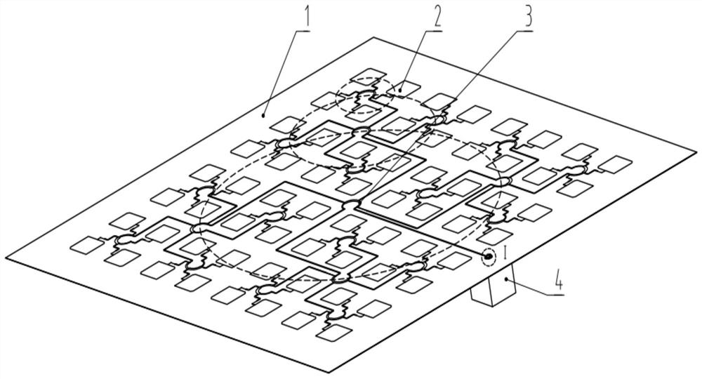
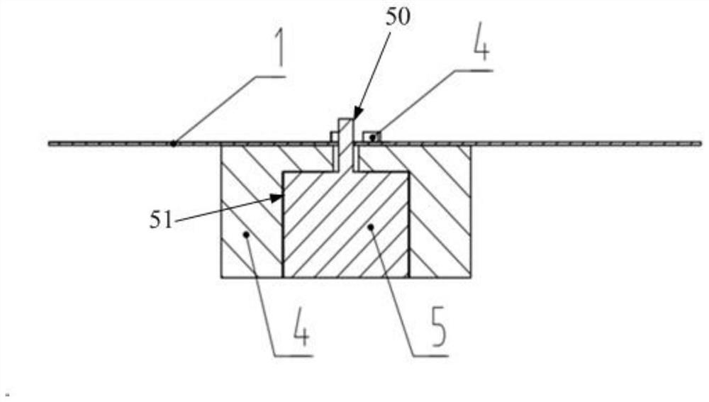
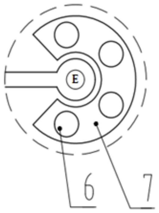
[0019] Such as figure 1 As shown, the present invention discloses a circularly polarized film antenna, including: a dielectric substrate 1, an antenna unit 2, a circularly polarized feed network 3 that rotates in sequence multiple times, a base 4, a radio frequency connector 5, a ground hole 6 and The ground strip line 7; the antenna unit 2 is distributed on the front (that is, the surface of the dielectric substrate 1) at a specific angle of rotation, and is fed by a circularly polarized feed network 3 that rotates in sequence multiple times. The upper and lower surfaces of the dielectric substrate 1 are covered with metal layer, the antenna unit 2 and the metal pattern required by the circularly polarized feed network 3 that rotates in sequence multiple times are formed on the upper surface of the dielectric substrate 1 by laser etching process, and the base 4 is connected to the grounding strip line on the dielectric substrate 1 through the ground hole 6 7 Carry out welding...


PUM

PropertyMeasurementUnit
thicknessaaaaaaaaaa
sizeaaaaaaaaaa
thicknessaaaaaaaaaa

Abstract

The invention provides a circularly polarized thin film antenna, which comprises a dielectric substrate, a plurality of antenna units, a multi-time sequential rotation circularly polarized feed network and a radio frequency connector, and is characterized in that the plurality of antenna units are mounted on the dielectric substrate, the antenna units are distributed on an array plane at a specific rotation angle, and the antenna units are fed by the multi-time sequential rotation circularly polarized feed network; the upper and lower surfaces of the dielectric substrate are covered with metal layers, and the upper surface of the dielectric substrate is etched with an antenna unit and a metal pattern required by a multi-circularly polarized feed network; and the radio frequency connector is connected with the multi-circularly polarized feed network. The circularly polarized thin film antenna has the beneficial effects that the antenna units of the circularly polarized thin film antenna adopt the rectangular grid layout, the four units are taken as the subarrays, each unit in the subarrays is sequentially rotated by 90 degrees to be distributed, and meanwhile, the circularly polarized feed network is sequentially rotated for multiple times, so that the antenna has the characteristics of wide standing wave bandwidth and axial ratio bandwidth.

Description

technical field [0001] The invention relates to the technical field of antennas, in particular to a circularly polarized film antenna. Background technique [0002] With the gradual maturity of 5G communication technology and the development of 6G communication, commercial satellites and satellite communications will be widely popularized. As an important sensor for satellites, space-borne antennas will also be developed. In view of the complex working environment and high launch costs of satellites, more and more attention has been paid to and researched on high-performance antennas that can be accommodated. The film antenna has the characteristics of foldable storage and takes up less space. After the satellite is launched, the antenna can be unfolded and then in working state. The film antenna belongs to the category of microstrip antenna. Using appropriate technology, different forms of antenna can be designed to meet the purpose. Therefore, film antennas have been exte...

Claims


Application Information

Patent Timeline
Patent Type & Authority Applications(China)
IPC IPC(8): H01Q1/38H01Q1/12H01Q1/48H01Q1/50H01Q21/00
Inventor 李春朱瑞龙谢成清高尔远贾朝锋
Owner AEROSPACE DONGFANGHONG DEV LTD
Why Eureka
Eureka Blog
Learn More