Intelligent electrical power distribution cabinet

A technology for intelligent electrical and power distribution cabinets, applied in substations/distribution device casings, hydraulic/pneumatic audible signals, instruments, etc. question

Active Publication Date: 2022-04-08
XUZHOU ZHONGTIE ELECTRIC
View PDF8 Cites 2 Cited by
  • Summary
  • Abstract
  • Description
  • Claims
  • Application Information

AI Technical Summary

Problems solved by technology

[0004] In view of the deficiencies in the use of the existing intelligent power distribution cabinet proposed in the background technology, the present invention provides an intelligent electric power distribution cabinet, which is equipped with cooling air sprayed to cool the electrical components, and the heat of the electrical components is absorbed and expanded by the heat absorbing pipe Internal air, when the carbon dioxide storage tank is on fire, carbon dioxide gas is ejected from the carbon dioxide storage tank, and the carbon dioxide gas impacts the valve plate to make the valve plate displace to open the carbon dioxide flow channel, close the cooling air flow channel, and the valve plate pushes up to block the piston, so that the cooling air flows into the alarm pipe, cooling air The impact metal reed sends out an alarm, the metal reed oscillates to make the extrusion piston perform suction movement, the extrusion piston pressurizes the carbon dioxide gas, the expansion gas pushes the sliding tube to open the carbon dioxide ejection airway, and the carbon dioxide is quickly ejected for fire extinguishing treatment Advantages, solve the technical problems of poor cooling effect in the power distribution cabinet, fast aging of electrical components, and poor fire treatment effect in the above-mentioned background technology

Method used


Image

  • Intelligent electrical power distribution cabinet
  • Intelligent electrical power distribution cabinet
  • Intelligent electrical power distribution cabinet

Examples


Embodiment Construction

[0023] The following will clearly and completely describe the technical solutions in the embodiments of the present invention with reference to the accompanying drawings in the embodiments of the present invention. Obviously, the described embodiments are only some, not all, embodiments of the present invention. Based on the embodiments of the present invention, all other embodiments obtained by persons of ordinary skill in the art without making creative efforts belong to the protection scope of the present invention.

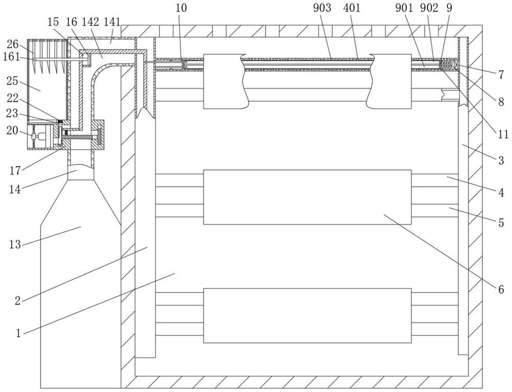
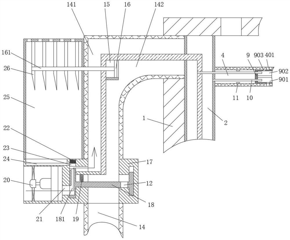
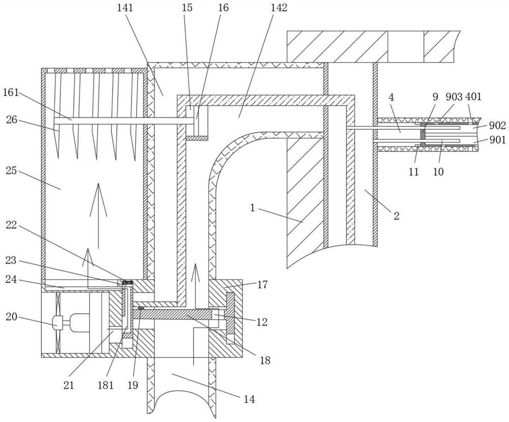
[0024] see figure 1 , Figure 4-Figure 5 , an intelligent electrical power distribution cabinet, including a cabinet 1, an intelligent controller is provided in the cabinet 1, and an exhaust hole is opened on the top of the cabinet 1, so that the gas that enters the cabinet 1 can be exhausted, so as to avoid the pressure of the gas and cause the internal Increased air pressure affects the normal operation of electrical components. One end of the inner cavity ...


PUM


Abstract

The invention relates to the technical field of electrical automation, and discloses an intelligent electrical power distribution cabinet, which comprises a cabinet, one end of an inner cavity of the cabinet is fixedly connected with a gas distribution pipe, the other end of the inner cavity of the cabinet is fixedly connected with a heat transfer pipe, and an electrical assembly is fixedly connected in the cabinet. Through the designed valve seat, the breather pipe, the communicating pipe, the spraying pipe and the sliding pipe, when the electrical assembly operates normally, the fan assembly can absorb external air to cool the electrical assembly through the sliding pipe and the spraying pipe, and meanwhile through the designed heat absorption pipe and the designed carbon dioxide storage tank, when the electrical assembly operates, the heat absorption pipe can absorb heat, so that the heat absorption effect is good. When the electric assembly is continuously heated to be burnt, the intelligent sensor can open a valve and an electric control valve of the carbon dioxide storage tank, a valve seat is pushed by gas to change a gas conveying valve opening, the expanded gas pushes a sliding pipe to change a gas spraying path, and the gas spraying path is changed. And therefore, the spraying pipe sprays carbon dioxide for fire extinguishing treatment.

Description

technical field [0001] The invention relates to the technical field of electrical automation, in particular to an intelligent electrical distribution cabinet. Background technique [0002] Intelligent electrical power distribution cabinet is a power distribution cabinet that comprehensively collects all energy data for the energy end of the data center computer room. It uses an intelligent controller for power distribution management, adding operation management and safety management that traditional power distribution cabinets do not have . [0003] Although the existing intelligent electrical distribution cabinets use temperature sensor accessories to monitor the temperature in the cabinet in real time, the cooling process in the cabinet still uses the traditional air convection cooling, which integrates a large number of electrical components in the intelligent distribution cabinet. When the heat dissipated is larger, sufficient heat dissipation effect cannot be obtained...

Claims


Application Information

Patent Timeline
Patent Type & Authority Applications(China)
IPC IPC(8): H02B1/30H02B1/28A62C3/16A62C31/00G08B3/06G08B21/24
Inventor 曹光振
Owner XUZHOU ZHONGTIE ELECTRIC
Why Eureka
Try Eureka