Angle-variable distraction fusion cage

A cage and angle technology, applied in spinal implants and other directions, can solve the problems of difficult implantation of diseased intervertebral space, large volume, falling off, etc., to reduce damage to vertebral body bone structure and soft tissue, reduce surgical risks, and maintain stability. sexual effect

Inactive Publication Date: 2022-04-12
SHANDONG WEIGAO ORTHOPEDIC DEVICE COMPANY
View PDF0 Cites 0 Cited by
  • Summary
  • Abstract
  • Description
  • Claims
  • Application Information

AI Technical Summary

Problems solved by technology

[0003] There are still some deficiencies in the actual use of the existing cages that can be distracted, for example: (1) Generally, the cages that are distracted in parallel do not conform to the lumbar intervertebral space Provincial shape, poor fit with the upper and lower vertebral body; (2) Large size, difficult to implant into the diseased intervertebral space, easy to damage the vertebral bone structure and soft tissue during implantation, and easy to excessively stretch the nerve and dural sac (3) Bone grafting first and then implantation, there is a risk of falling off during the implantation process

Method used


Image

  • Angle-variable distraction fusion cage
  • Angle-variable distraction fusion cage
  • Angle-variable distraction fusion cage

Examples


Embodiment Construction

[0037] In order to make the purpose, technical solutions and advantages of the embodiments of the present invention more clear, the technical solutions in the embodiments of the present invention will be clearly and completely described below in conjunction with the drawings in the embodiments of the present invention.

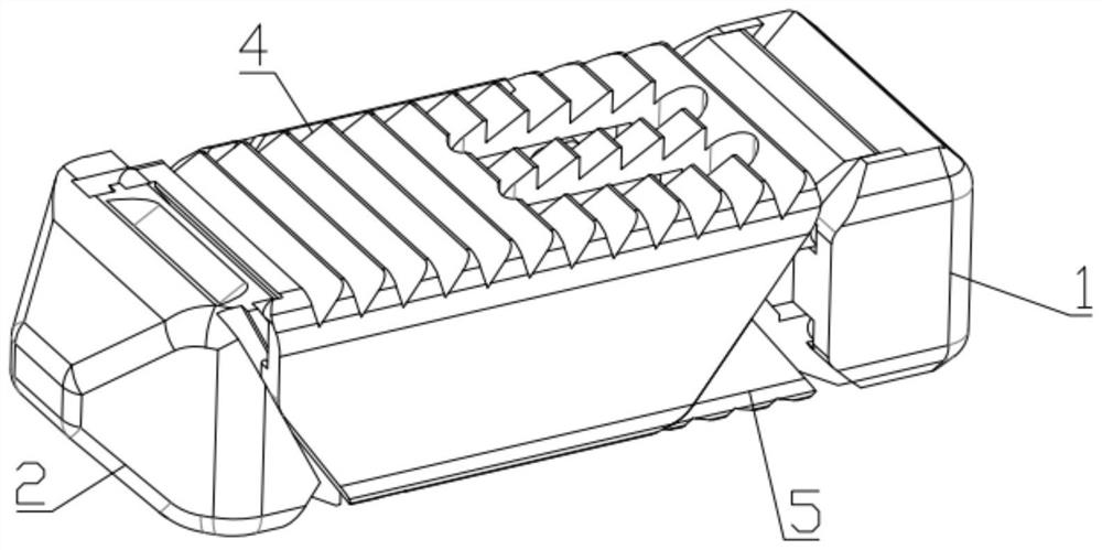
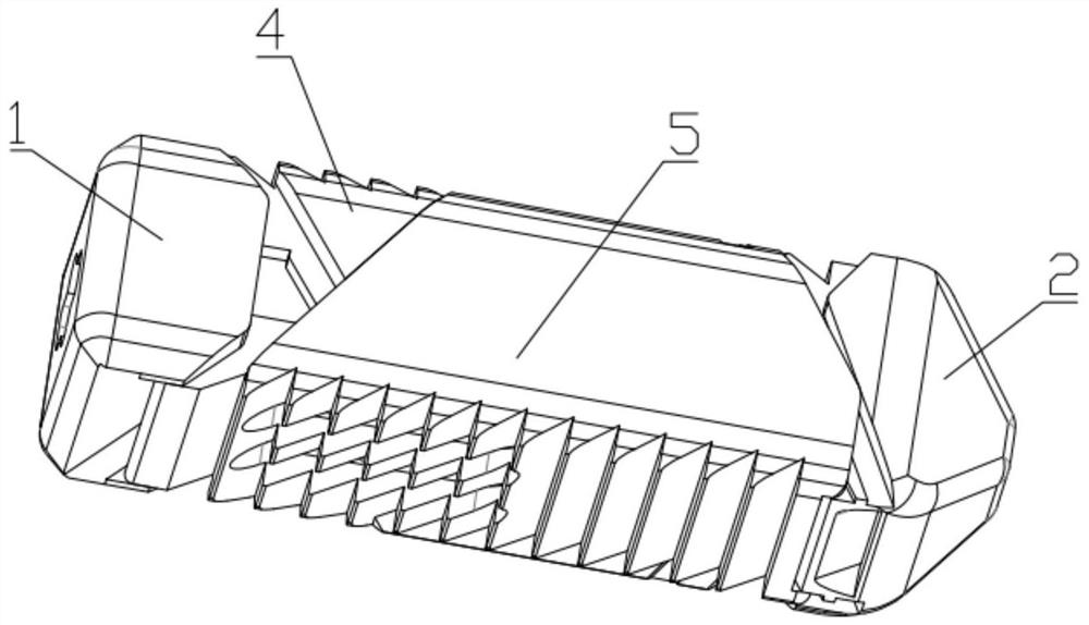
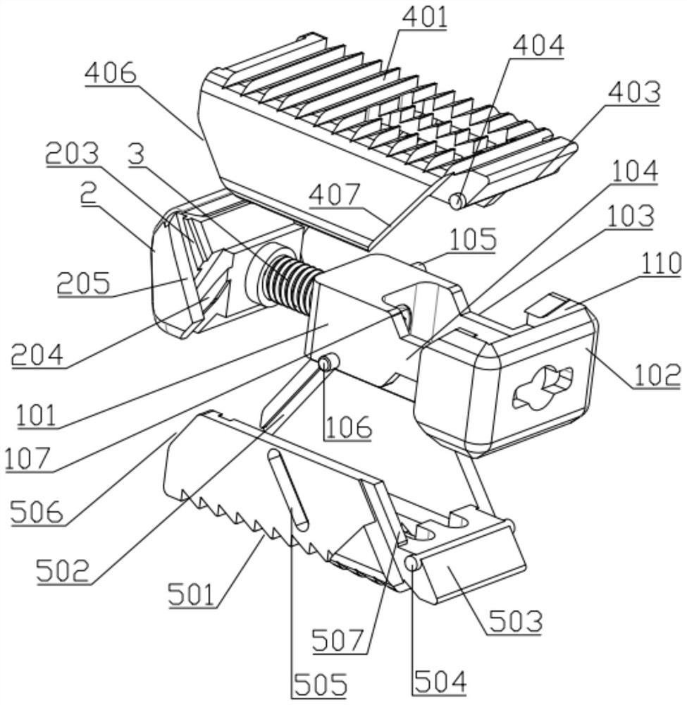
[0038] Such as Figure 1-14 In the illustrated embodiment, a variable-angle distraction cage includes a cage body 1, a cage head 2, screws 3, an upper cover 4 and a lower cover 5, wherein:

[0039] The fuse body 1 includes a front mounting block 101, a rear mounting block 102, a left connecting block 103 arranged between the left end faces of the front mounting block 101 and the rear mounting block 102, and a left connecting block 103 arranged between the front mounting block 101 and the rear mounting block 102. The right connecting block 104 between the right end faces of the front mounting block 101; the upper cover plate guide post 105 or the lower cover pl...


PUM


Abstract

The invention relates to the technical field of medical instruments, in particular to a variable-angle distraction fusion cage. The angle-variable distraction fusion cage comprises a fusion cage main body, a fusion cage head, a screw, an upper cover plate and a lower cover plate. The screw crown of the screw is screwed through a tool, under the action of the limiting ring, the screw only rotates in the circumferential direction, the head of the fusion cage is pulled to move towards the front mounting block, under the limitation of the upper cover plate and the lower cover plate, the head of the fusion cage translates towards the front mounting block, and in the translation process, an upper cover plate head guide block and an upper cover plate head guide groove slide in a matched mode; the front end of the upper cover plate is lifted, meanwhile, the upper guide column slides along the transverse groove of the guide groove in the tail portion of the upper cover plate, the process is the angle changing process, then the upper guide column slides along the inclined groove of the guide groove in the tail portion of the upper cover plate, the upper cover plate is opened in parallel at an angle, and the opening process of the lower cover plate is similar. The variable angle of the front end better conforms to the physiological form of the lumbar intervertebral space, and the device can be easily implanted into the lesion intervertebral space.

Description

technical field [0001] The invention relates to the technical field of medical instruments, in particular to a variable-angle distraction fusion device. Background technique [0002] Degenerative changes of the spine are more common in orthopedic clinics. The common ones are intervertebral disc degeneration, spinal stenosis, spondylolisthesis, and those who compress the spinal cord or nerve roots often require surgical treatment to completely relieve the compression, restore the physiological curvature of the spine, and ensure spinal stability. In addition, some patients with spinal deformity, trauma, tumor, revision surgery and infection sometimes need intervertebral fusion to stabilize the lumbar segment. The intervertebral fusion device has a good curative effect on the above spinal diseases. It is simple to operate, easy to use, has a high fusion rate, and has no complications of bone graft fusion. It has been widely used in clinical practice. [0003] There are still s...

Claims


Application Information

Patent Timeline
Patent Type & Authority Applications(China)
IPC IPC(8): A61F2/44
Inventor 张彬王利君郑晓义
Owner SHANDONG WEIGAO ORTHOPEDIC DEVICE COMPANY
Why Eureka
Try Eureka