[0004] For example, the patent number is: 2019105249032, which is a Chinese invention patent for a
fully automatic inverted direct push ball cage groove special milling machine. The sliding seat is equipped with a workpiece spindle. The workpiece spindle adopts a high-speed torque-type electric spindle with a clamp at the end, a rotary table on the front side of the
bed, and a swing shaft on the rotary table. There is a slide rail at the end, a slide table is installed on the slide rail, a
linear motor drive is installed inside the slide table, a tool electric spindle is installed on the slide table, a loading machine and an unloading machine are installed behind the
bed, and a There are workpiece grabbing manipulators and workpiece transporting manipulators arranged vertically; the above invention can complete the milling of multiple grooves with any inclination of the
constant velocity universal joint ball cage in one clamping, but this milling machine has the following disadvantages: 1 , The tool swings to the set angle through the swing shaft of the rotary table, but because the swing shaft is placed horizontally, and the end of the swing shaft is provided with a linear slide rail, the slide table is installed on the linear slide rail, and the inside of the slide table It is driven by a
linear motor, and the tool electric spindle is installed on the slide table, which is equivalent to the swing axis bearing the weight of the linear slide rail, slide table,
linear motor drive and tool electric spindle, as well as the
cutting tool and
constant velocity universal joint ball cage. The reaction force of the
cutting force during the feed movement, under the pressure accumulated over time, the center line of the swing shaft is bound to be locally bent or deformed, or even broken, which will lead to changes in the position of the tool motorized spindle, which in turn will cause the machined groove Deviations will affect the product accuracy, and more seriously, it will cause equipment damage; 2. The tool can swing to the set angle through the swing axis of the rotary table, and then the linear motor drives the slide table to drive the tool electric spindle to realize oblique milling. By setting the swing angle, grooves with any slope can be processed. From this technology, it can be directly obtained that: this technology can process linear grooves with any slope. If this is the case, the swing axis of the rotary table needs to be in a constantly swinging position, and the slide table is continuously reciprocating up and down on the linear slide rail to perform feed motion, which has the following disadvantages: ①. The tool electric spindle is fixed on the slide table, and the slide table and The linear slide rail is slidingly connected, the linear slide rail is fixed on the swing shaft, and the swing shaft is rotationally connected with the rotary table, and the position accuracy of the tool electric spindle cannot be guaranteed due to multiple movable connections
②. This technology is similar to the traditional solution. During the process of machining the groove, the tool is performing both the main movement and the feed movement, and the position of the workpiece does not change, so as to achieve cutting of the workpiece, which in turn causes the tool to vibrate and shake easily
3. Since the swing axis bears the weight of the linear slide rail, slide table, linear
motor drive and tool electric spindle, as well as the reaction force of the
cutting force during the cutting feed movement of the tool and the constant velocity
universal joint ball cage, the swing will be relatively large. It is laborious, and it is even more difficult to do a coherent circular arc movement. At the same time, the power requirements for the driving components are very large, and the
energy consumption is also large.
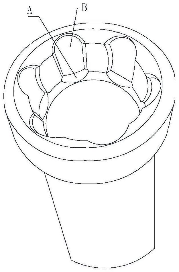
4. There is only one tool electric spindle, so it is impossible to process the above-mentioned double arc groove at one time. If all the
processing cannot be completed by one milling machine, the position is easy to shift after the second clamping, and then Causes the relative position between the second arc channel (B) and the first arc channel (A) to change, affecting the machining accuracy

