Multi-legged robot

A multi-legged robot and robot technology, applied in robot-related fields, can solve problems such as difficulty in realizing robot body control, difficulty in assembling robots, and poor robot motion performance, and achieve strong terrain adaptability, strong adaptability, and high running speed Effect

Pending Publication Date: 2022-04-12
ZHEJIANG UNIV HANGZHOU GLOBAL SCI & TECH INNOVATION CENT
6 Cites 0 Cited by

AI-Extracted Technical Summary

Problems solved by technology

How to combine the advantages of different configurations of legged robots is a difficult point to be solved. Chinese patent CN108638041A, a modular robot, discloses a technical solution to solve the above-mentioned difficulties by modularly assembling the robot, but the disclosed The connection method is a rigid connection, and it is a whole after assembly. Although the purpose of adjusting the number of feet can be achieved, it is difficult to give full play to the advantages of the assembled robot, and it is difficult to adjust th...

Method used

A kind of multi-legged robot of the present invention, as Fig. 1, comprises at least two robot units 1, and robot unit comprises frame 11, and control mechanism 12, driving mechanism 13 and foot 14 are installed on the frame, foot At least two groups are arranged, and the adjacent robot units are connected by a connection structure 2. The connection structure 2 includes a connection part 21 and an elastic part 22. The connection part 21 is connected to the robot unit 1, and the elastic part 22 is connected to the adjacent robot unit 1. The connecting part 21 is connected, and the elastic part 22 is used as the spine of the multi-legged robot. While realizing the modular assembly and freely adjusting the number of feet, it also enables the multi-legged robot to have a higher running speed potential with the elastic spine, and at the same speed In this way, the energy consumption is lower, the battery life is longer, the attitude adjustment of each robot unit 1 is more free, and the terrain adaptability is stronger.
Control mechanism 12 comprises airborne computer, is used to control the motion of robot unit, and this airborne computer is prior art, can directly purchase and obtain from the market, and concrete control logic program is also prior art, so in This will not go into details. The drive mechanism 13 includes an abduction joint motor 131, a hip joint motor 132 and a knee joint motor 133. A battery 15 is installed on the frame. The battery 15 is used ...

Abstract

The invention relates to the related technical field of robots, and discloses a multi-legged robot which comprises at least two robot units, each robot unit comprises a rack, a control mechanism, a driving mechanism and a foot part are installed on each rack, every two adjacent robot units are connected through a connecting structure, each connecting structure comprises a connecting part and an elastic part, and the connecting parts are connected with the connecting parts. The connecting parts are connected with the robot units, and the elastic parts are connected with the connecting parts on the adjacent robot units. According to the multi-legged robot, the elastic part is arranged to serve as the spine of the multi-legged robot, the multi-legged robot has the potential of higher running speed due to the elastic spine while modular assembly is achieved and the number of feet is freely adjusted, and under the same speed, the energy consumption is lower, the endurance is longer, and the posture adjustment of each robot unit is more free; and the terrain adaptability is higher.

Application Domain

Vehicles

Technology Topic

Mechanical engineeringRoboty +3

Image

  • Multi-legged robot
  • Multi-legged robot
  • Multi-legged robot

Examples

  • Experimental program(1)

Example Embodiment

[0024] Combine below Figure 1-4 The present invention will be described in detail.
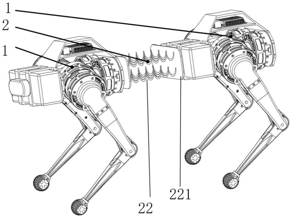
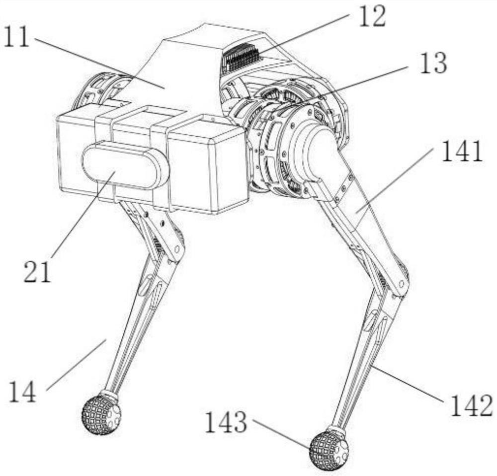
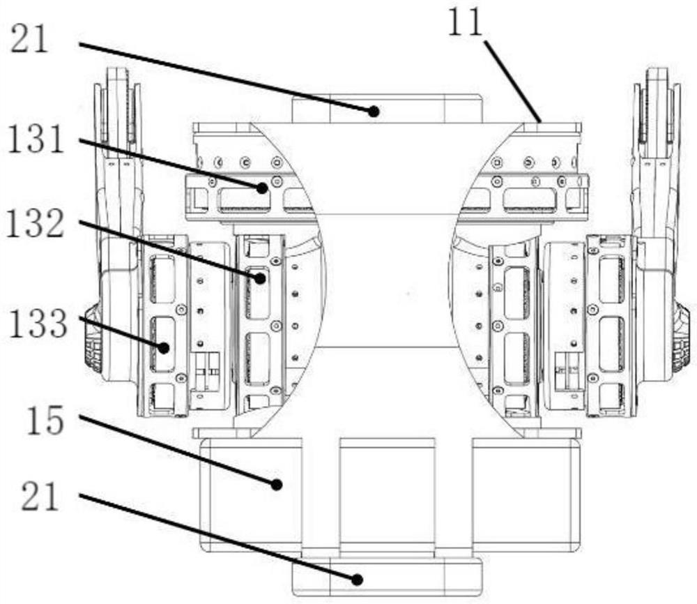
[0025] A multi-legged robot of the present invention, such as figure 1 , including at least two robot units 1, the robot unit includes a frame 11, a control mechanism 12, a drive mechanism 13 and a foot 14 are installed on the frame, at least two groups of feet are arranged, and a connecting structure 2 is passed between adjacent robot units Connected, the connecting structure 2 includes a connecting part 21 and an elastic part 22, the connecting part 21 is connected with the robot unit 1, the elastic part 22 is connected with the connecting part 21 on the adjacent robot unit 1, and the elastic part 22 is used as the spine of the multi-legged robot, While realizing the freedom to adjust the number of feet in modular assembly, it also enables the multi-legged robot to have a higher running speed potential with an elastic spine, and at the same speed, it has lower energy consumption and longer battery life. Each robot unit 1's attitude adjustment is more free, and the ability to adapt to terrain is stronger.
[0026] The connecting parts are respectively arranged on the front side, the rear side and/or the left side and the right side of the robot unit (with the two feet of the robot unit 1 as the left and right sides), and the assembly between the robot units 1 can be realized in multiple directions .
[0027] The connecting part may be a buckle structure, and the elastic part is provided with a matching structure connected with the buckle structure.
[0028] Preferably, the connecting part is an electromagnet, and an armature 221 is connected to the elastic part. The armature is plate-shaped and arranged at both ends of the elastic part. After the electromagnet generates magnetism, it is respectively connected with two armatures 221 to realize two adjacent robots. The connection between the units 1 is easy to disassemble, facilitate the combination of multi-legged robots, and facilitate the adjustment of the body stiffness of the multi-legged robot. Under certain circumstances, the elastic part 22 can be omitted, and the adjacent robot units 1 directly pass through the connecting part connect.
[0029] The control mechanism 12 includes an on-board computer for controlling the movement of the robot unit. The on-board computer is an existing technology and can be directly purchased from the market, and the specific control logic program is also an existing technology, so it will not be described here. To repeat, the drive mechanism 13 includes an abduction joint motor 131, a hip joint motor 132 and a knee joint motor 133, and a battery 15 is installed on the frame, and the battery 15 is used to provide energy for the drive mechanism 13 and the onboard computer, and the hip joint motor 132 is set In the middle of the frame 11, the abduction joint motor 131 and the battery 15 are distributed on both sides of the hip joint motor 132, that is, the abduction joint motor 131 and the battery 15 are distributed on the front and rear sides of the frame 11 to balance the center of gravity of the robot. As a function, the foot 14 includes a thigh 141, a shank 142 and a hoof 143, the shank 141 is rotatably connected with the thigh, and the hoof 143 is rotatably connected with the shank.
[0030] The calf 142 can adopt a retractable spring mechanism to imitate the function of the human ankle. On the one hand, it can be used for cushioning, and on the other hand, it can be used for energy storage, which not only improves terrain adaptability, but also increases the maximum speed.
[0031] The robot unit is equipped with a position adjustment mechanism, and the connecting part is installed on the position adjustment mechanism. The position adjustment mechanism is a three-dimensional adjustment device, and the adjustable direction includes one or several directions in the front and rear, up and down, and left and right directions. The position adjustment mechanism is specific. Including one or more structures in telescopic structure, horizontal rotation structure and vertical rotation structure, such as Figure 4 Shown is a robot structure with a vertical rotation structure 500 installed, the position adjustment mechanism is used to adjust the position of the connecting part relative to the frame 11, and the position adjustment mechanism actively drives and adjusts the relative positions of the connected front and rear robots in an active state , so as to achieve the following functions: 1. When running at high speed, the front and rear parts of the body can always be kept in the optimal relative posture, thereby achieving a higher running speed; 2. According to different terrains, the relative posture of the front and rear parts of the body can be actively adjusted , For example, for undulating terrain with large slope changes, the body posture can be adjusted like a snake to adapt to the terrain; 3. Part of the body can be stood up to expand the operating space of the robot; the position adjustment mechanism is in a passive state and does not actively adjust. The elastic part 22 works passively.
[0032] Preferably, several groups of elastic parts are provided.
[0033] Preferably, the elastic part can be a spring, an elastic sheet, an elastic material connection block, a multi-joint connecting rod with torsion springs at joints, and the like.
[0034] The above-mentioned embodiments are only to illustrate the technical concept and characteristics of the present invention, and the purpose is to enable those skilled in the art to understand and implement the present invention, and not to limit the protection scope of the present invention. All equivalent changes or modifications made according to the spirit of the present invention shall fall within the protection scope of the present invention.

PUM

no PUM

Description & Claims & Application Information

We can also present the details of the Description, Claims and Application information to help users get a comprehensive understanding of the technical details of the patent, such as background art, summary of invention, brief description of drawings, description of embodiments, and other original content. On the other hand, users can also determine the specific scope of protection of the technology through the list of claims; as well as understand the changes in the life cycle of the technology with the presentation of the patent timeline. Login to view more.

Similar technology patents

Method for preparing aluminum oxide from coal series kaolinite rock or coal gangue

InactiveCN101234774AReduce energy consumptionSave resources and energy
Owner:EAST CHINA UNIV OF SCI & TECH

System for controlling functions of a vehicle by speech

InactiveUS20140297060A1simple hardwarereduce energy consumption
Owner:GM GLOBAL TECH OPERATIONS LLC

Classification and recommendation of technical efficacy words

  • Reduce energy consumption
  • Improve battery life

Apparatus and method for controlling fluid flow

InactiveUS6948697B2reduce energy consumptionincrease battery longevity
Owner:SLOAN VALVE COMPANY

Preparation method of high-strength hydrogel

InactiveCN103739861AThe preparation process takes a short timeReduce energy consumption
Owner:HENAN POLYTECHNIC UNIV

Catalyst for gas phase hydrogenation of acetic acid to prepare ethanol

Owner:DALIAN INST OF CHEM PHYSICS CHINESE ACAD OF SCI +1

Universal micro electromechanical system (MEMS) pedometer and step counting method

InactiveCN103148864AThe circuit is simple and reliableImprove battery life
Owner:HARBIN ENG UNIV

Electric car and bi-directional inversion type motor controller

InactiveCN104786866AImprove battery lifewidely used
Owner:深圳电擎科技有限公司

Method, device and system for reducing power consumption of Type-C interfaces

PendingCN107122037AImprove battery lifeProtection life
Owner:SHENZHEN COOLHEAR INFORMATION TECH CO LTD
Why Eureka
Try Eureka