Syringe dispensing device for hematology department
A technology for syringes and blood, which is applied in the direction of unloading devices, transportation and packaging, and types of packaged items, which can solve the problems of low efficiency of medical staff and achieve the effect of protecting blood
- Summary
- Abstract
- Description
- Claims
- Application Information
AI Technical Summary
Problems solved by technology
Method used
Image
Examples
Embodiment 1
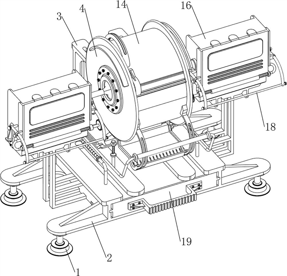
[0035] A syringe dispensing device for hematology, such as Figure 1-6 As shown, it includes a fixed pile 1, a support plate 2, a first fixed column 3, a material storage box 4, a sliding material pallet 5, a first pull rod 6, a first slide rod 7, a first linear spring 8, a first Wedge block 9, the second wedge block 10, the second slide bar 11, the second linear spring 12, baffle plate 13, material feeding mechanism 14 and material pushing mechanism 15, the left and right sides of the support plate 2 bottoms are equipped with fixed Pile 1, the rear side of the support plate 2 is symmetrically provided with the first fixed column 3, the storage box 4 is connected between the first fixed column 3, the front side of the storage box 4 is provided with a sliding material pallet 5, and the support plate 2 The top left and right sides are symmetrically provided with the first slide bar 7, and the first slide bar 7 is provided with the first wedge-shaped block 9 slidingly, and the fi...
Embodiment 2
[0038] On the basis of Example 1, such as figure 1 , figure 2 , image 3 , Figure 7 and Figure 8 As shown, the feeding mechanism 14 includes a slide plate 141, a slide rail 142, a first slide block 143 and a second pull rod 144, and the front and rear sides of the top of the material storage box 4 are provided with slide rails 142. There are first sliders 143 , and a slider 141 is connected between the first sliders 143 , and a second pull rod 144 is provided on the left side of the top of the first slider 141 .
[0039] The user can pull the slide plate 141 and the first slider 143 through the second pull rod 144, and then the top of the storage box 4 is opened, and the user can place the syringe in the storage box 4. After the placement is completed, the user passes the second pull rod 144 Just pull the sliding plate 141 and the first sliding block 143 in opposite directions.
[0040] The pushing mechanism 15 includes a second fixed column 151, a push plate 152, a th...
Embodiment 3
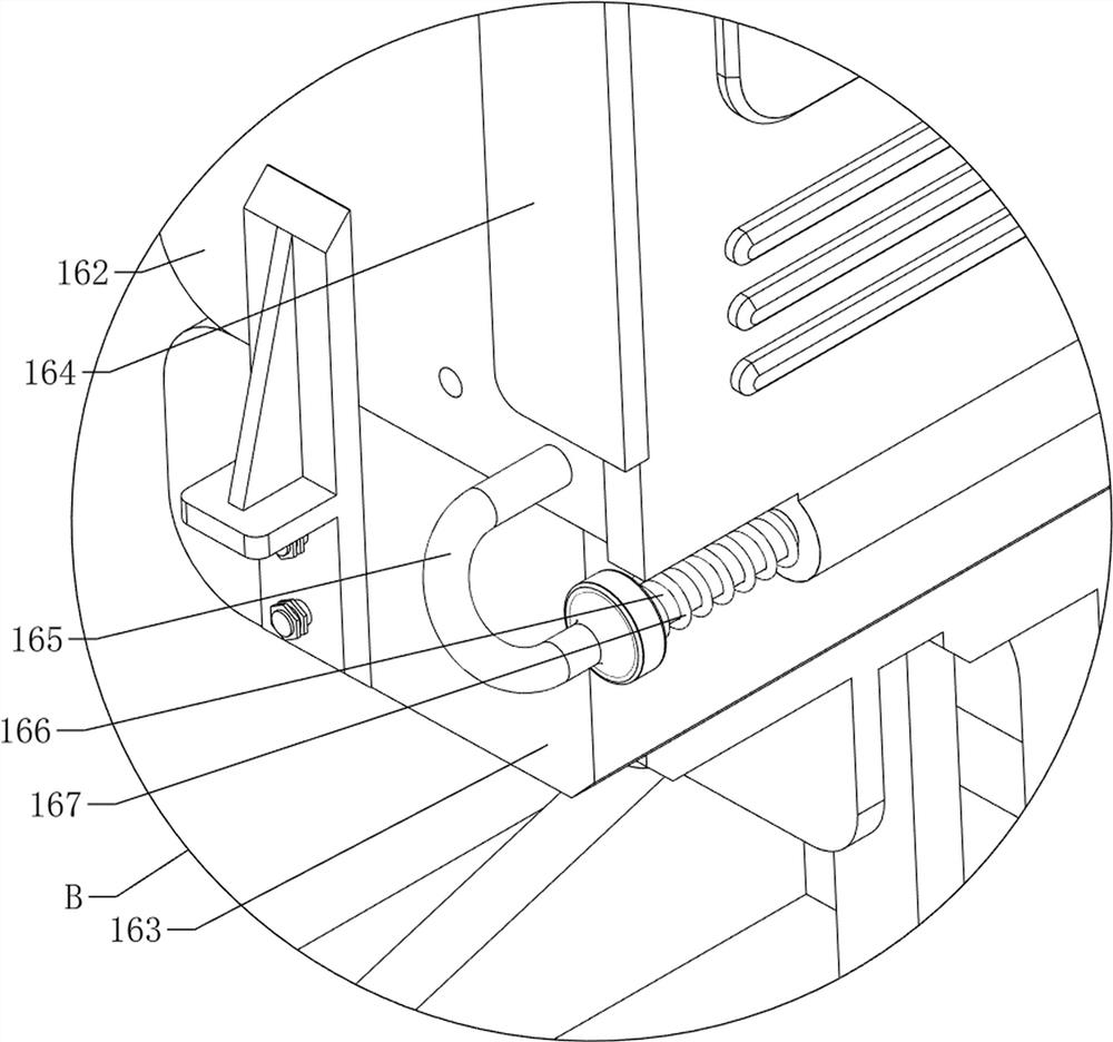
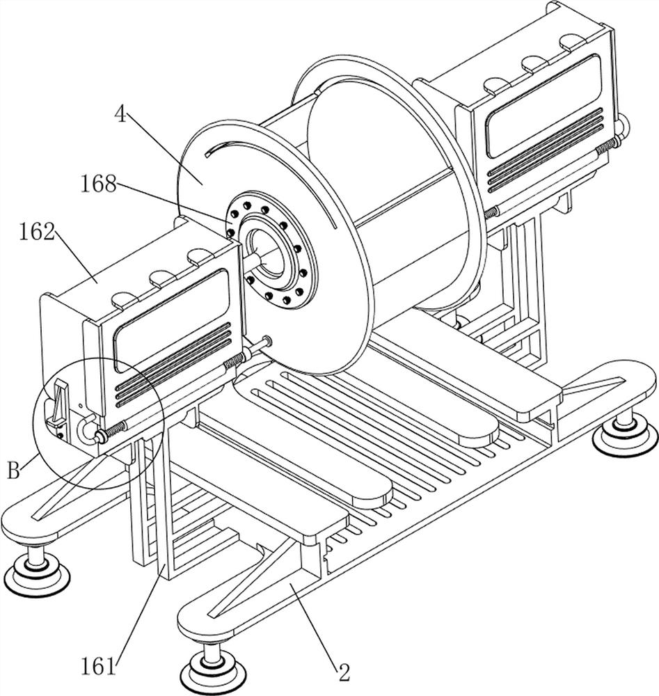
[0043] On the basis of Example 2, such as figure 1 , figure 2 , image 3 , Figure 9 , Figure 10 , Figure 11 , Figure 12 , Figure 13 , Figure 14 and Figure 15 As shown, also include placing mechanism 16, and placing mechanism 16 includes the 3rd fixed column 161, placed box 162, constant temperature box 163, separating plate 164, the 4th fixed column 165, the first rotating shaft 166, the first torsion spring 167, The fifth fixed column 168 and the air pipe 169, the third fixed column 161 is provided on the left and right sides of the support plate 2, the thermostat 163 is provided on the top of the third fixed column 161, and the fifth fixed column 163 is provided on the left and right sides of the material storage box 4. Fixed post 168, the fifth fixed post 168 is equipped with a placement box 162, the placement case 162 is connected with the incubator 163, and the lower side position of the left and right sides of the placement box 162 is provided with the fo...
PUM
 Abstract
Description
Claims
Application Information
 - R&D
- Intellectual Property
- Life Sciences
- Materials
- Tech Scout
- Unparalleled Data Quality
- Higher Quality Content
- 60% Fewer Hallucinations
Browse by: Latest US Patents, China's latest patents, Technical Efficacy Thesaurus, Application Domain, Technology Topic, Popular Technical Reports.
© 2025 PatSnap. All rights reserved.Legal|Privacy policy|Modern Slavery Act Transparency Statement|Sitemap|About US| Contact US: help@patsnap.com


