Supercharge Your Innovation With Domain-Expert AI Agents!

Method and apparatus for sputter deposition

A sputtering target, plasma technology, applied in the field of sputtering deposition

Pending Publication Date: 2022-04-12
DYSON TECH LTD
View PDF10 Cites 0 Cited by
  • Summary
  • Abstract
  • Description
  • Claims
  • Application Information

AI Technical Summary

Problems solved by technology

Axis of plasma generation

Method used


Image

  • Method and apparatus for sputter deposition
  • Method and apparatus for sputter deposition
  • Method and apparatus for sputter deposition

Examples


Embodiment Construction

[0050] Reference in the specification to "an example" (or "an embodiment" or similar language) means that a particular feature, structure, or characteristic described in connection with the example is included in at least one example but not necessarily other examples. It should also be noted that certain embodiments are described schematically, with certain features omitted and / or simplified as necessary, in order to facilitate explanation and understanding of the concepts behind the embodiments.

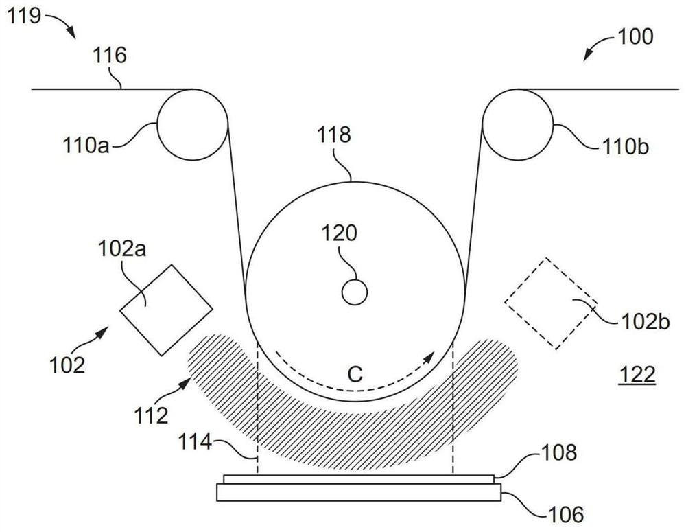
[0051] refer to figure 1 , illustrates an example apparatus 100 for sputter deposition of a target material 108 onto a substrate 116 . Apparatus 100 may be considered an example of a plasma reactor. Apparatus 100 can be used for plasma-based sputter deposition in a variety of industrial applications, such as those that can be used for thin film deposition, for example in optical coatings, magnetic recording media, electronic semiconductor devices, LEDs, thin film solar cells and o...


PUM

PropertyMeasurementUnit
thicknessaaaaaaaaaa
thicknessaaaaaaaaaa
diameteraaaaaaaaaa

Abstract

A method of making a layer of material on a surface is disclosed. The method includes the step of a spiral plasma source generating a plasma away from the at least one sputtering target in a plasma generation region and along a plasma generation axis. The helical plasma source includes (a) one or more antennas and (b) one or more permanent magnets arranged to generate a magnetic field proximate the magnets, the magnetic field along a plasma generation axis and in a plasma generation region. The plasma causes the material to be ejected from the sputtering target. The method includes a step of depositing a material jetted from a sputtering target onto a surface of a substrate or a surface supported by the substrate to form a material layer on the surface.

Description

technical field [0001] The present invention relates to sputter deposition, and more particularly to methods and apparatus for sputter deposition of target materials onto surfaces using remotely generated plasma. Background technique [0002] Deposition is a process by which a target material is deposited on a surface, such as a substrate. An example of deposition is thin film deposition, in which thin layers (typically from about a nanometer or even a fraction of a nanometer to a few micrometers or even tens of micrometers) are deposited on a substrate, such as a silicon wafer or a coil. One example technique for thin film deposition is physical vapor deposition (PVD), in which a target material in a condensed phase is vaporized to generate a vapor that is then condensed onto a substrate surface. One example of PVD is sputter deposition, in which particles are ejected from a target as a result of being bombarded by energetic particles such as ions. In the example of sputt...

Claims


Application Information

Patent Timeline
Patent Type & Authority Applications(China)
IPC IPC(8): C23C14/35H01J37/32
CPCH01J37/3211H01J37/321H01J37/32669H01J37/3266H01J37/3277H01J37/34H01M4/139H01M2004/021H01M4/0402H01M10/052H01M10/058C23C14/35Y02E60/10H01M4/0426
Inventor S.高特
Owner DYSON TECH LTD
Features
  • R&D
  • Intellectual Property
  • Life Sciences
  • Materials
  • Tech Scout
  • Unparalleled Data Quality
  • Higher Quality Content
  • 60% Fewer Hallucinations
Learn More