Post-grouting device for prestressed concrete pipe pile

A technology of concrete pipe piles and post-grouting, which is applied in the direction of sheet pile walls, buildings, and foundation structure engineering. Simple, eliminate the effect of external interference

Pending Publication Date: 2022-04-12
福建建中岩土工程有限责任公司
View PDF0 Cites 2 Cited by
  • Summary
  • Abstract
  • Description
  • Claims
  • Application Information

AI Technical Summary

Problems solved by technology

In order to solve this problem, the existing technology combines the post-grouting technology of cast-in-place piles to improve the cost performance of pile foundations, expands the application range and improves the application effect, and proposes that the post-grouting technology can be used to improve the bearing capacity of pipe piles; at present, in the existing technology Most of the post-grouting devices for pipe piles are post-grouting devices that can only achieve post-grouting at the pile side or post-grouting at the bottom of the pile, which can only improve the bearing performance of the pile foundation. On the outside of the grouting device, it is difficult to insert into the soil layer, and there are problems that it is difficult to ensure that the bearing capacity of the pipe pile is up to standard after construction, and the construction is difficult; therefore, it is necessary to develop a new post-pile grouting device

Method used


Image

  • Post-grouting device for prestressed concrete pipe pile
  • Post-grouting device for prestressed concrete pipe pile
  • Post-grouting device for prestressed concrete pipe pile

Examples


Embodiment 1

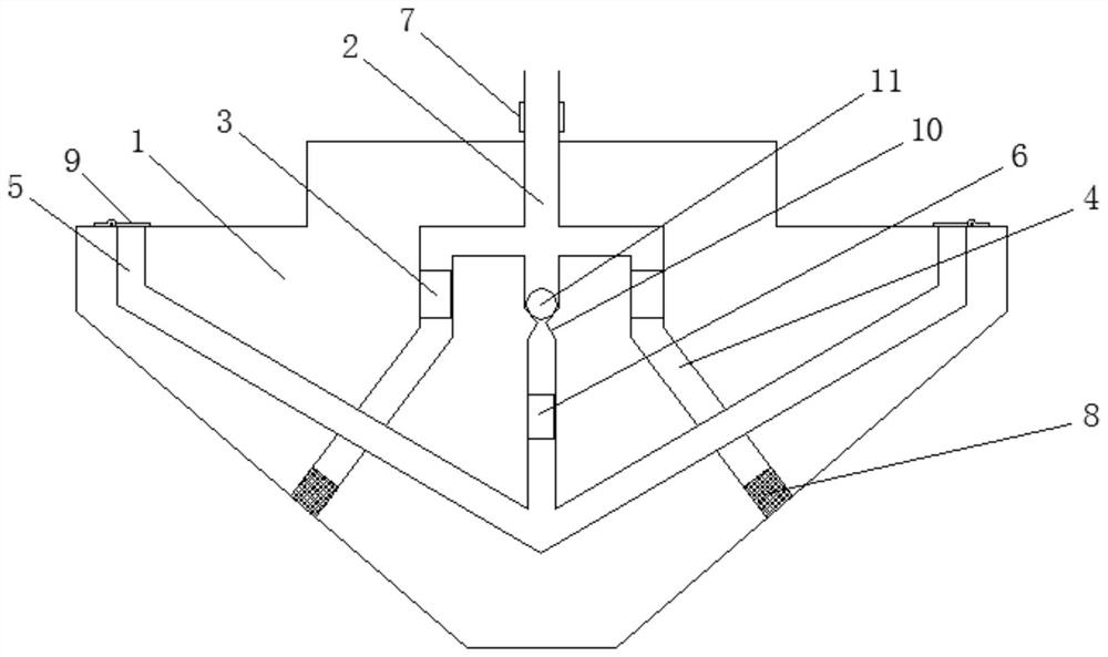
[0028] Example 1: Please refer to figure 1 , the present embodiment provides a post-grouting device for prestressed concrete pipe piles, including a grouting device body 1, and the grouting device body 1 is arranged in an inverted conical structure, so that the grouting device body 1 can be inserted into the soil layer easily, and at the same time , in order to ensure the structural strength of the grouter body 1, the grouter body 1 is made of reinforced concrete and then poured with concrete, and the strength grade should reach C30, so as to ensure that the grouter body 1 is not easy to break during work; The inside of the grouter body 1 is provided with a vertical main grouting channel 2, the top of the main grouting channel 2 passes out from the top surface of the grouter body 1, and the main grouting channel 2 passes from the grouter body 1 The outer wall of the pipe passing through the top surface is provided with a pipe clamp screw 7, which is used to facilitate the conn...

Embodiment 2

[0032] Since the grouting on the side of the pile and the grouting on the bottom of the pile are carried out at the same time in embodiment 1, there may be a problem that the amount of grouting is difficult to control. Based on this, embodiment 2 is proposed;

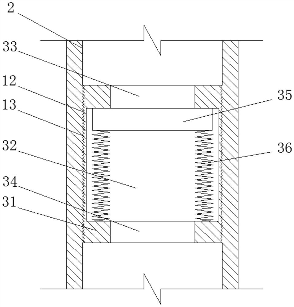
[0033] Example 2: Please refer to Figure 1~6 , this embodiment provides a post-grouting device for prestressed concrete pipe piles, including all the structures in Embodiment 1, and also includes the following structures: the middle part of the pile side grouting channel 5 and the middle part of the bottom of the main grouting channel 2 A variable diameter structure 10 is provided at the position where the bifurcation part is connected, and a steel ball 11 is also provided in the middle bifurcation part of the bottom of the main grouting channel 2. The diameter of the steel ball 11 is larger than the diameter of the variable diameter structure 10, so that the steel ball 11 can adjust the The structure 10 plays a blocki...


PUM


Abstract

The invention relates to the technical field of building construction, and discloses a prestressed concrete pipe pile post-grouting device which comprises a grouting device body, a main grouting channel is formed in the grouting device body, the bottom of the main grouting channel is of a three-fork-shaped structure, and first check valves are arranged in forked parts on the two sides of the bottom of the main grouting channel correspondingly; pile bottom grouting channels penetrating through the side walls of the two sides of the grouting device body are further connected to the forked parts on the two sides of the bottom of the main grouting channel, pile side grouting channels arranged in a three-fork-shaped structure are further formed in the grouting device body, and the forked parts on the two sides of the pile side grouting channels penetrate out of the positions, close to the ends of the two sides, of the top face of the grouting device body; the middle bifurcated part of the pile side grouting channel is communicated with the middle bifurcated part of the bottom of the main grouting channel, and a second check valve is further connected into the middle bifurcated part of the pile side grouting channel; the method has the characteristics that the bearing capacity effect of the pipe pile after construction reaches the standard, and construction is simple.

Description

technical field [0001] The invention relates to the technical field of building construction, in particular to a post-grouting device for prestressed concrete pipe piles. Background technique [0002] Prestressed concrete pipe piles have the advantages of reliable pile quality, fast construction speed, low cost per unit bearing capacity, and civilized construction site. At present, in the weak soil layer, the bearing capacity provided by the resistance of the surrounding soil of the pipe pile is much smaller than the design bearing capacity of the pile body structure, resulting in the problem that the strength of the pile body material cannot be fully exerted. The main reasons for this problem are: ( 1) Due to the influence of soil plugging effect, the end resistance of pipe piles is small, and the long-term stability is poor; (2) The outer surface of pipe piles is very smooth, and the high-density concrete has poor soil affinity and small side resistance, especially in satu...

Claims


Application Information

Patent Timeline
Patent Type & Authority Applications(China)
IPC IPC(8): E02D15/02E02D5/58
Inventor 唐文池文旭伍捷卢雨雪陈雪峰郑素娟余翠萍邹青青徐桂芳池乾恒陈安叶兴叶阿春蔡志强许丹妮
Owner 福建建中岩土工程有限责任公司
Why Eureka
Try Eureka