Vibration reduction column composite foundation for subway station and vibration reduction method of vibration reduction column composite foundation

A composite foundation and subway station technology, which is applied to the composite foundation of the vibration damping column for the subway station and its vibration reduction field, can solve the problem of reducing the comfort of pedestrian subway traffic facilities, endangering the overall structural safety of the subway station, and increasing the overall cost of the subway station, etc. problems, to achieve the effect of preventing long-term vibration cracking, avoiding natural vibration, and compact structure

Active Publication Date: 2022-04-12
SOUTHEAST UNIV
View PDF6 Cites 0 Cited by
  • Summary
  • Abstract
  • Description
  • Claims
  • Application Information

AI Technical Summary

Problems solved by technology

[0003] The impact caused by structural vibration is various. On the one hand, it will reduce the comfort of pedestrians using subway transportation facilities, further affecting the orderly progress of daily production and life, and on the other hand, it will endanger the safety of the overall structure of the subway station.
[0004] The vibration reduction of traditional rail transit structures is achieved by strengthening the main structures such as auxiliary beams, columns, and walls to achieve the purpose of vibration reduction. This vibration reduction design increases the overall cost of the subway station and increases the difficulty of later maintenance. In the case of strong vibration, unfavorable structural diseases such as collapse and toppling are prone to occur. Therefore, it is necessary to design from the perspective of the far end of the structure, such as the foundation of the column, to meet the vibration damping performance of the overall structure

Method used


Image

  • Vibration reduction column composite foundation for subway station and vibration reduction method of vibration reduction column composite foundation
  • Vibration reduction column composite foundation for subway station and vibration reduction method of vibration reduction column composite foundation

Examples


Embodiment Construction

[0047] The technical solutions of the present invention will be described in further detail below in conjunction with the accompanying drawings and specific embodiments.

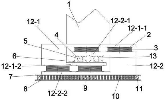
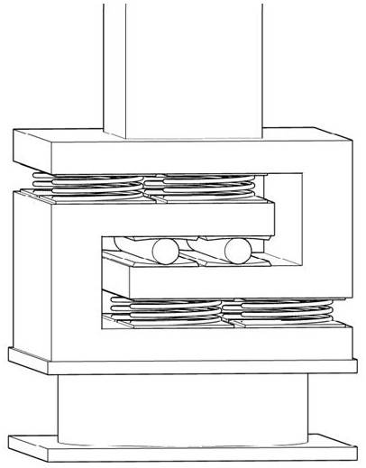
[0048] The present invention includes cylinder 1, anti-slip and wear-resistant rubber sheet 2, low-frequency spray plastic spring 3, upper connecting concave plate 4, steel rod 5, lower connecting concave plate 6, upper connecting plate 7, lower connecting plate 8, lead rod 9, Viscoelastic composite steel plate structure 10, durable rubber 11, special-shaped U-shaped support and rolling wear structure 13;

[0049] The energy-dissipating composite structure at the bottom of the foundation is preset to connect the upper connecting plate 7 and the lower connecting plate 8; a lead rod 9 without pores and impurities inside, wear-resistant and compressive is inserted in the center of the energy-dissipating composite structure at the bottom of the foundation.

[0050] The viscoelastic composite steel plate structur...


PUM


Abstract

The invention discloses a vibration reduction column composite foundation for a subway station and a vibration reduction method thereof, and the vibration reduction column composite foundation comprises a foundation bottom energy dissipation composite structure located at the bottommost part of the whole foundation; the two special-shaped U-shaped supports are arranged on the upper portion of the foundation bottom energy dissipation composite structure and comprise the first special-shaped U-shaped support and the second special-shaped U-shaped support, and the first special-shaped U-shaped support comprises a first upper horizontal supporting plate and a first lower horizontal supporting plate which are arranged in parallel; a lead rod is arranged in the center of the foundation bottom energy dissipation composite structure, and the two sides of the lead rod are each of a multi-layer viscous-elastic material composite steel plate structure. Vibration generated by the whole station can be effectively reduced, the multi-layer and multi-dimensional vibration reduction effect is achieved, the main structure of the station is effectively prevented from cracking due to long-term vibration, and the safety of long-term operation is guaranteed.

Description

technical field [0001] The invention relates to the field of vibration reduction of rail transit structures, and relates to a composite foundation of a vibration-damping column for a subway station and a vibration-damping method thereof. Background technique [0002] The structural vibration of the overall structure of the subway station under the excitation of pedestrian loads and train operation has gradually become a key consideration in the design. Firstly, it is the floor vibration caused by the pedestrian load, and secondly, it is the structural vibration caused by the train operating conditions. Vibration reduction mainly avoids resonance by coordinating the vibration frequency of the overall structure and the exciting force of rail trains. On this basis, the resonance frequency can be avoided or far lower than the resonance frequency by changing the composition of the overall structure or selecting components with different stiffnesses. the goal of. [0003] The imp...

Claims


Application Information

Patent Timeline
Patent Type & Authority Applications(China)
IPC IPC(8): E02D27/42E02D31/08E02D29/045
Inventor 金浩王智弘
Owner SOUTHEAST UNIV
Why Eureka
Try Eureka