Plane steel truss node connecting device

A node connection and steel truss technology, which is applied in the field of planar steel truss node connection devices, can solve the problem that the number and angle of the rods that can be installed at the connection node cannot be adjusted on site, so as to avoid quality defects, clear force transmission path, and quick replacement Effect

Pending Publication Date: 2022-04-12
CHINA RAILWAY NO 5 ENG GRP BUILDING ENG +1
View PDF12 Cites 0 Cited by
  • Summary
  • Abstract
  • Description
  • Claims
  • Application Information

AI Technical Summary

Problems solved by technology

[0005] The technical problem to be solved by the present invention is to provide a space node connection device that can adjust the included angle and number in view of the problem that the current connection node cannot adjust the number and angle of the rods that can be installed on site

Method used


Image

  • Plane steel truss node connecting device
  • Plane steel truss node connecting device
  • Plane steel truss node connecting device

Examples


Embodiment 1

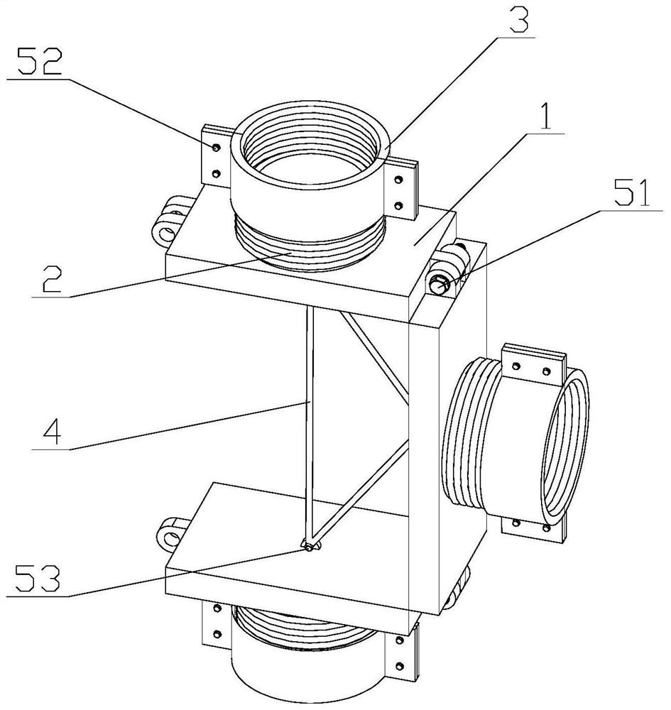
[0039] The planar steel truss node connection device provided by the present invention includes any number of connection units, and one connection unit includes an end plate 1 , a steel sleeve 2 , a detachable round pipe 3 , a flat head brace 4 , and a bolt 5 .

[0040] The end plate 1 includes a base 11 , a pair of circular platform clamping grooves 12 on the left, a single boss 13 on the right and a single anchoring seat 14 at the bottom.

[0041] The base 11 is a cuboid steel block, the length of which can be prefabricated according to the position of the planar rod, the width is slightly larger than the steel sleeve 2, and the thickness needs to be determined according to calculation, so as to ensure that the base will not be damaged by punching and shearing.

[0042] The circular platform clamping groove 12 is composed of two bosses 13, and the bosses 13 are composed of a cuboid and a half cylinder, and the height of the cuboid is consistent with the diameter of the half c...

Embodiment 2

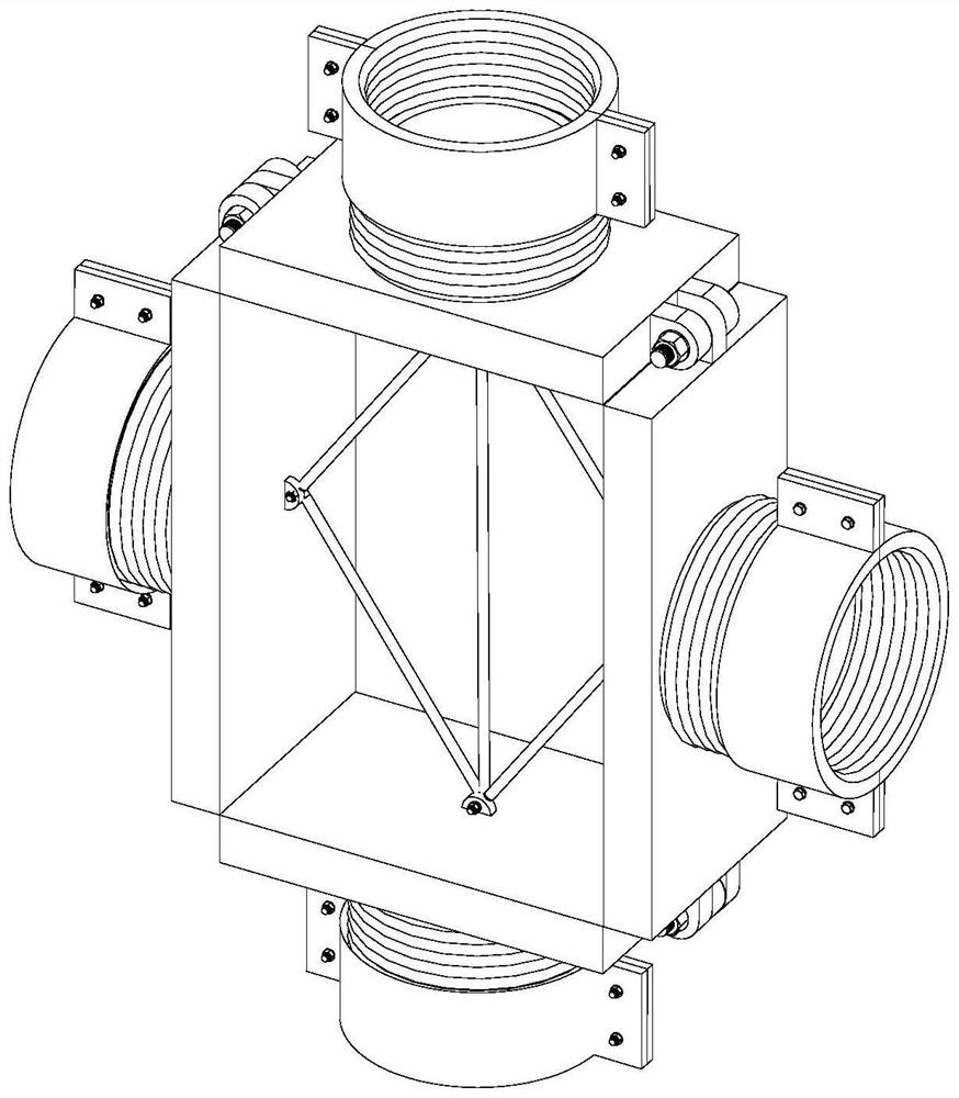
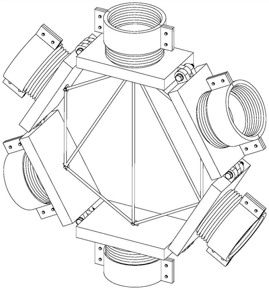
[0049] preferred embodiment, such as figure 1 , figure 2 , image 3 As shown, this embodiment includes an end plate 1, a steel sleeve 2, a detachable round pipe 3, a flat head strut 4, and a bolt 5, and is suitable for connection of any number of round pipes at any angle on the plane.

[0050] Such as figure 1 As shown, the end plate 1 includes a base 11, a circular platform clamping groove 12, a boss 13 and an anchoring platform 14, which can be mass-produced in advance in the factory.

[0051] Such as Figure 4 As shown, the base 11 is a cuboid solid steel plate, its main function is to transmit force, bear the external force transmitted by the steel truss tube, the adjacent end plate 1, and the flat head brace 4, and its length is determined according to the position of the plane steel truss tube. Ensure that all the end plates 1 of the whole device can be hinged into a body, and its width is 2 to 4 cm larger than the outer diameter of the steel sleeve 2, and the thick...


PUM


Abstract

The invention discloses a plane steel truss joint connecting device which comprises bases, steel sleeves are installed on the upper surfaces of the bases, bosses are arranged on the two sides of the bases, anchoring pedestals are arranged on the lower surfaces of the bases, detachable round pipes are installed on the steel sleeves, three or more bases are connected and spliced into a joint, and the two sides of the joint are connected through the bosses and round table clamping grooves by bolts. When the device is put into use, the number of the connecting units and the lengths of the end plates and the flat-head supporting rods are determined according to site requirements, then all the end plates are rotated and positioned around the first bolts, then the two semicircular pipes are sequentially clamped with the steel sleeve and the plane truss circular pipe at the same time, the four bolts on the side plates are tightened, and a detachable circular pipe is formed; by rotating the detachable round pipe, the plane truss round pipe is close to the steel sleeve, stress adjustment of the rod pieces is achieved, finally the flat-head supporting rod is anchored, geometric invariant stable nodes are formed, and therefore connection of any number of rod pieces at any angle in the plane is achieved.

Description

technical field [0001] The invention belongs to the technical field of building construction, and in particular relates to a joint connection device of a plane steel truss. Background technique [0002] In recent years, with the acceleration of my country's modernization process, prefabricated structures have been widely used in the construction industry. Its biggest feature is factory prefabrication, on-site assembly, short construction period, and high degree of mechanization. Among them, the prefabricated steel truss structure is one of the mainstream building structures in my country. The roof trusses and awnings of many large venues mostly adopt the prefabricated steel truss structure. Convenience, welds, bolts or rivets are often used to connect each component or part. [0003] However, in the actual construction process on site, there are also some difficulties in the prefabricated structure, such as: heavy welding workload, weld quality cannot be guaranteed, stress c...

Claims


Application Information

Patent Timeline
Patent Type & Authority Applications(China)
IPC IPC(8): E04B1/24E04B1/58E04C3/04
Inventor 周晨邓正云杨俊谭占进左勇健贺磊龚仲毅周建云蒋丽忠江力强
Owner CHINA RAILWAY NO 5 ENG GRP BUILDING ENG
Why Eureka
Try Eureka