Moving blade design method, moving blade and steam turbine for driving air separation compressor

A design method and technology of moving blades, which are applied to the supporting elements of blades, engine elements, machines/engines, etc., can solve the problems of low design efficiency, high design cost of moving blades, and high equipment costs of moving blades, and reduce procurement costs. Simplify the design difficulty and process, the effect of small dynamic stress

Pending Publication Date: 2022-04-12
HANGZHOU STEAM TURBINE
View PDF4 Cites 0 Cited by
  • Summary
  • Abstract
  • Description
  • Claims
  • Application Information

AI Technical Summary

Problems solved by technology

[0004] The purpose of this application is to provide a method for designing a moving blade, a moving blade and a steam turbine driving an air separation compressor, so as to solve to a certain extent the high design cost and low design efficiency of the moving blade in the prior art, resulting in a The technical problem of high equipment cost of the blade

Method used


Image

  • Moving blade design method, moving blade and steam turbine for driving air separation compressor
  • Moving blade design method, moving blade and steam turbine for driving air separation compressor
  • Moving blade design method, moving blade and steam turbine for driving air separation compressor

Examples


Embodiment 1

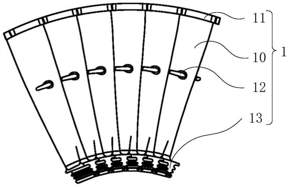
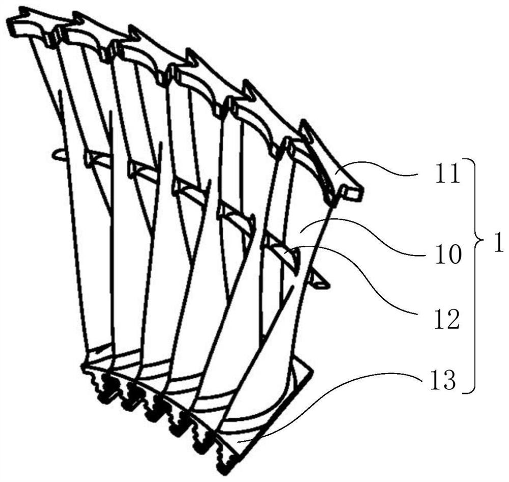
[0046] see Figure 1 to Figure 3 As shown, the embodiment of the present application provides a method for designing a moving blade including the following steps:

[0047] Step S100, the moving blade 1 is designed to include the blade root 13, the blade body 10 and the shroud 11, the blade root 13 and the shroud 11 are respectively connected to the bottom and the top of the blade body 10, and the blade body 10 and the blade root 13 are used as Basic Department;

[0048] In step S200, the disk assembly is designed to include the disk of the rotor and a plurality of moving blades 1 arranged around the disk of the rotor, the blade root 13 of each moving blade 1 is connected to the disk of the rotor, and every two adjacent The shrouds 11 of each moving blade 1 abut against each other;

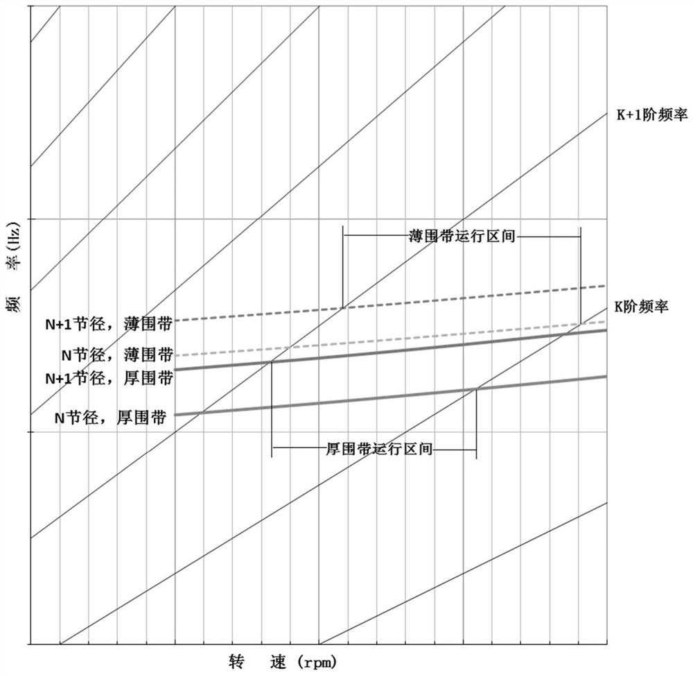
[0049] Step S300, determining the target operating interval;

[0050]Step S400, keep the basic part of the roulette assembly unchanged, adjust the parameters of the shroud 11 of the roulette ass...

Embodiment 2

[0080] see Figure 1 to Figure 3 As shown, the second embodiment provides a moving blade 1, which is designed by the design method of the moving blade in the first embodiment, and the technical features of the design method of the moving blade disclosed in the first embodiment are also applicable to this embodiment , the technical features of the disclosed rotor blade design method in Embodiment 1 will not be described repeatedly.

[0081] The moving blade 1 in this embodiment has the advantages of the design method of the moving blade in the first embodiment, and the advantages of the design method of the moving blade disclosed in the first embodiment will not be repeated here.


PUM


Abstract

The invention relates to the technical field of steam turbine moving blade equipment, in particular to a moving blade design method, a moving blade and a steam turbine for driving an air separation compressor. The moving blade design method comprises the following steps that a moving blade is designed to comprise a blade root, a blade body and a shroud ring, and the blade body and the blade root serve as a base part; the wheel disc assembly is designed to comprise a wheel disc and a plurality of moving blades surrounding the wheel disc; keeping the basic part of the wheel disc assembly unchanged, continuously adjusting the parameters of the shroud ring, and solving the resonance rotating speed avoiding interval of the wheel disc assembly for avoiding the triple key points; and determining the moving blade design result as the moving blade corresponding to the wheel disc assembly until the target operation interval falls into the resonance rotating speed avoiding interval of the wheel disc assembly. The moving blade is designed according to a moving blade design method. A steam turbine driving the air separation compressor includes a rotor blade. The invention relates to a moving blade design method, a moving blade and a steam turbine for driving an air separation compressor. A shaped blade which only operates in a specific operation interval is improved into a universal blade which meets various operation intervals.

Description

technical field [0001] The present application relates to the technical field of steam turbine moving blade equipment, in particular to a design method of a moving blade, a moving blade and a steam turbine driving an air separation compressor. Background technique [0002] The full-circle self-locking damping blade has good performance in reducing resonance vibration stress. The basic structure of the full-circle self-locking damping blade is a single-piece structure with a shroud on the blade top. [0003] However, at present, the whole circle of self-locking damping blades is usually re-designed according to the needs of each application, and the design cost is high and the design cycle is long, resulting in high production costs for the manufacturer's moving blades. Contents of the invention [0004] The purpose of this application is to provide a method for designing a moving blade, a moving blade and a steam turbine driving an air separation compressor, so as to solve...

Claims


Application Information

Patent Timeline
Patent Type & Authority Applications(China)
IPC IPC(8): F01D5/10F01D5/14F01D5/16F01D15/08
Inventor 刘象拯丁旭东闫志勇高骥郭则传
Owner HANGZHOU STEAM TURBINE
Why Eureka
Try Eureka