
Vibrating water pump with upper water inlet and lower water inlet

A double water inlet and water pump technology, applied in the direction of pumps, pump components, non-variable pumps, etc., can solve problems such as limited water inlet, difficulty in realizing fast water outlet operations with large displacement, and water pumps that cannot work normally. Simple, improve water inlet efficiency and quality, reasonable design effect

Pending Publication Date: 2022-04-12
浙江耀鼎泵业股份有限公司
View PDF0 Cites 0 Cited by
  • Summary
  • Abstract
  • Description
  • Claims
  • Application Information

AI Technical Summary

Problems solved by technology

At present, the water pumps on the market mainly include a water inlet and a water outlet. The negative pressure of the water inlet is realized through the internal mechanism, and then the liquid is sucked from the water inlet and then discharged from the water outlet. The defect of this structure is: only setting A single water inlet, when the water inlet is blocked, the entire water pump cannot work normally, and the water inflow per unit time of a single water inlet is limited, and it is difficult to achieve rapid water discharge with large displacement

Method used


Image

  • Vibrating water pump with upper water inlet and lower water inlet
  • Vibrating water pump with upper water inlet and lower water inlet
  • Vibrating water pump with upper water inlet and lower water inlet

Examples


Embodiment Construction

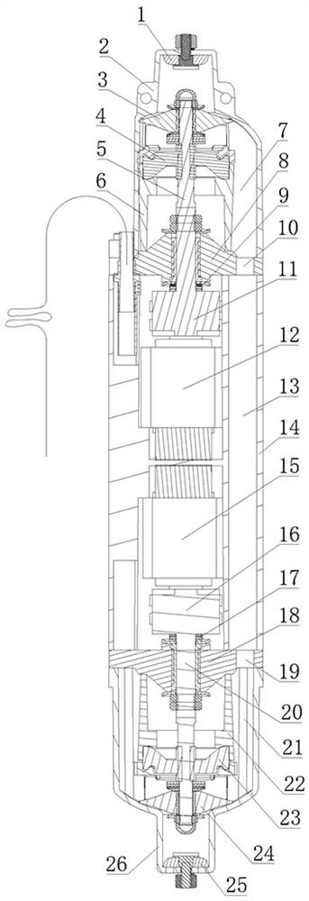
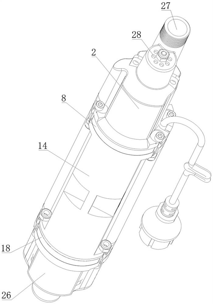
[0018] As shown in the figure, a vibrating water pump with upper and lower water inlets disclosed by the present invention includes an outer casing, the outer casing includes an upper cover 2, a barrel 14 and a lower cover 26, and the upper cover 2 is provided with an upper water inlet hole 28 and an outlet. The water outlet 27, the lower cover 26 is provided with a lower water inlet 29, the upper cover 2 is provided with a first one-way valve at the upper water inlet 28, and the lower cover 26 is provided with a second one-way valve at the lower water inlet 29 Specifically, the first one-way valve is a first rubber flap 1, and the first rubber flap 1 is installed inside the upper cover 2. The first rubber flap 1 can block the upper water inlet hole 28, and the second rubber flap 1 can block the upper water inlet hole 28. The one-way valve is a second rubber baffle 25, and the second rubber baffle 25 is installed inside the lower cover 26, and the second rubber baffle 25 can bl...


PUM


Abstract

The upper and lower double-water-inlet vibration water pump comprises an outer shell, the outer shell comprises an upper cover, a machine barrel and a lower cover, an upper water inlet hole and a water outlet are formed in the upper cover, a lower water inlet hole is formed in the lower cover, a first one-way valve is arranged at the position of the upper water inlet hole in the upper cover, and a second one-way valve is arranged at the position of the lower water inlet hole in the lower cover; an upper water chamber communicated with the upper water inlet hole and the water outlet is arranged in the upper cover, a lower water chamber communicated with the lower water inlet hole is arranged in the lower cover, a through hole flow channel communicated with the upper water chamber and the lower water chamber is arranged in the machine barrel, and a first impeller is arranged at the position, corresponding to the first one-way valve, in the upper water chamber. A second impeller is arranged in the lower water chamber corresponding to the second one-way valve, and a power assembly capable of driving the first impeller and the second impeller to swing back and forth is arranged in the machine barrel. The water pump is simple in structure, reasonable in design and capable of achieving two-way water inflow, the water inflow efficiency of the water pump is further improved, and then the water yield and the water outflow stability are improved.

Description

technical field [0001] The invention relates to a water pump, in particular to a vibrating water pump with upper and lower water inlets. Background technique [0002] A pump is a machine that transports or pressurizes a liquid. At present, the water pumps on the market mainly include a water inlet and a water outlet. The negative pressure of the water inlet is realized through the internal mechanism, and then the liquid is sucked from the water inlet and then discharged from the water outlet. The defect of this structure is: only setting A single water inlet, when the water inlet is blocked, the whole water pump will not work normally, and the water intake per unit time of the single water inlet is limited, and it is also difficult to realize the fast water outlet operation of large displacement. Contents of the invention [0003] In view of the deficiencies in the background technology, the technical problem to be solved by the present invention is to provide a high-effi...

Claims


Application Information

Patent Timeline
IPC IPC(8): F04D33/00F04D29/40
Inventor 王亨利
Owner 浙江耀鼎泵业股份有限公司
Learn More