End face driving bevel gear tooth-shaped connecting structure

A connection structure and bevel tooth technology, which is applied to components with teeth, belts/chains/gears, portable lifting devices, etc., can solve the problems of small force-bearing surface, complicated process, easy to generate noise, etc., and shorten the shaft The size, the manufacturing process is simple, and the effect of avoiding stress concentration

Pending Publication Date: 2022-04-12
耐世特凌云驱动系统(涿州)有限公司
View PDF0 Cites 0 Cited by
  • Summary
  • Abstract
  • Description
  • Claims
  • Application Information

AI Technical Summary

Problems solved by technology

[0002] The face gear mainly transmits motion and power through the continuous meshing of the teeth. It is one of the most widely used transmission methods in modern equipment and the automotive industry. At present, the face teeth are straight grooves and straight teeth made directly on the end face of the shaft. In order to It does not cause changes in other parameters of the shaft, the length of the teeth and grooves is shorter, the force-bearing surface becomes smaller, the transmission stability is poor, the wear resistance is poor, and the service life is short
Moreover, the end faces of the two end face teeth meshed together are all flat, and the flatness of the plane is poor, resulting in more contact positions of points or lines, which further causes the force bearing surface to become smaller, poor transmission stability and wear resistance, and short life
The flatness of the plane is poor, and it is easy to generate noise during the transmission process, which affects the comfort of the entire transmission system
Due to the high requirements on flatness of the plane, the whole process is complicated
There is no automatic centering function, which is easy to cause deviation caused by different concentricity of the connecting parts, causing the rotating connecting parts to jump; in order to ensure the service life, the axial dimension is large, which is not suitable for the occasion of higher speed and higher power rotating connection use

Method used


Image

  • End face driving bevel gear tooth-shaped connecting structure
  • End face driving bevel gear tooth-shaped connecting structure
  • End face driving bevel gear tooth-shaped connecting structure

Examples


Embodiment Construction

[0020] The present invention will be further described below in conjunction with specific embodiments.

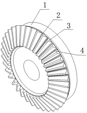
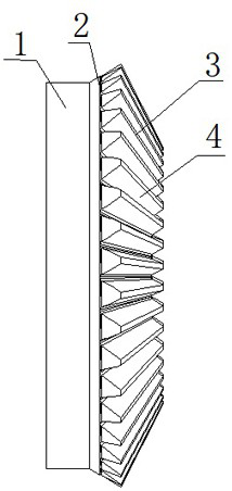
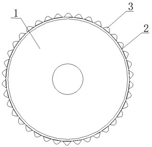
[0021] Such as Figure 1 to Figure 12 As shown, this embodiment includes component I1 and component II5 with completely matched parameters. The outer end of the end face of component I1 is a circumscribed and inclined circular-shaped inclined plane I2. On the inclined plane I2, there are a plurality of inclined bevel teeth I3 evenly protruding outward. Between the bevel teeth I3 is a bevel groove I4. Groove I4 forms a bevel gear. The outer end of the end face of component II5 is a concave and inclined circular-shaped inclined plane II6. The slope II6 has the same width and inclination angle as the slope I2. On the slope Ⅱ6, there are evenly indented conical grooves Ⅱ7 with the same number as the bevel teeth Ⅰ3 and matching with the bevel teeth Ⅰ3. Between the bevel grooves Ⅱ7 are bevel teeth Ⅱ8 matching with the bevel grooves Ⅰ4. Each bevel tooth Ⅱ8 and each bevel Taper...


PUM


Abstract

The invention discloses an end face driving bevel gear tooth-shaped connecting structure which is characterized in that the outer end of the end face of a component I is an externally tangent inclined annular inclined face I, a plurality of inclined bevel gears I are evenly and outwards arranged on the annular inclined face I in a protruding mode, bevel grooves I are formed between the bevel gears I, and bevel gears are formed by the bevel gears I and the bevel grooves I; the outer end part of the end surface of the part II is a concave and inclined ring-shaped inclined surface II; the inclined plane II and the inclined plane I have the same width and inclination angle; conical grooves II which are the same as the conical teeth I in number and are matched with the conical teeth I are uniformly and inwards concavely formed in the inclined surface II, conical teeth II matched with the conical grooves I are arranged among the conical grooves II, and each conical tooth II and each conical groove II form an inwards concave bevel gear; and the component I and the component II are axially compressed, and the bevel gear and the concave bevel gear are completely meshed together. The invention has the advantages of large stress area, good transmission stability, strong wear resistance and long service life; the self-centering function is achieved, jumping generated by rotation is avoided, noise is low, and the self-centering rotary joint is suitable for being used in occasions with higher rotating speed and higher power rotary connection.

Description

technical field [0001] The invention relates to an end-face driving bevel gear tooth-shaped connection structure. Background technique [0002] The face gear mainly transmits motion and power through the continuous meshing of the teeth. It is one of the most widely used transmission methods in modern equipment and the automotive industry. At present, the face teeth are straight grooves and straight teeth made directly on the end face of the shaft. In order to It does not cause changes in other parameters of the shaft, the length of the teeth and grooves is shorter, the force-bearing surface becomes smaller, the transmission stability is poor, the wear resistance is poor, and the service life is short. And the end faces of the two end face teeth meshed together are all planes, and the flatness of the planes is poor, resulting in more contact positions of points or lines, which further causes the force bearing surface to become smaller, poor transmission stability and wear res...

Claims


Application Information

Patent Timeline
Patent Type & Authority Applications(China)
IPC IPC(8): F16H55/17
Inventor 李月郭宇张静龙
Owner 耐世特凌云驱动系统(涿州)有限公司
Why Eureka
Try Eureka