Electronic component processing equipment and method

A technology for electronic components and processing equipment, applied in the field of electronic components processing equipment, can solve the problems of incomplete drying, reduce performance, affect production efficiency, etc., to improve work efficiency and performance, reduce frictional resistance, reduce The effect of small limitations

Active Publication Date: 2022-04-12
淮安市宝鼎科技有限公司
View PDF7 Cites 2 Cited by
  • Summary
  • Abstract
  • Description
  • Claims
  • Application Information

AI Technical Summary

Problems solved by technology

[0004] In order to solve the above technical problems, the present invention provides an electronic component processing equipment and method, which solves the problem that the existing drying equipment for electronic component processing has a slow drying speed and poor adaptability to parts and components. Afterwards, they will stick together, and

Method used


Image

  • Electronic component processing equipment and method
  • Electronic component processing equipment and method
  • Electronic component processing equipment and method

Examples


Embodiment 1

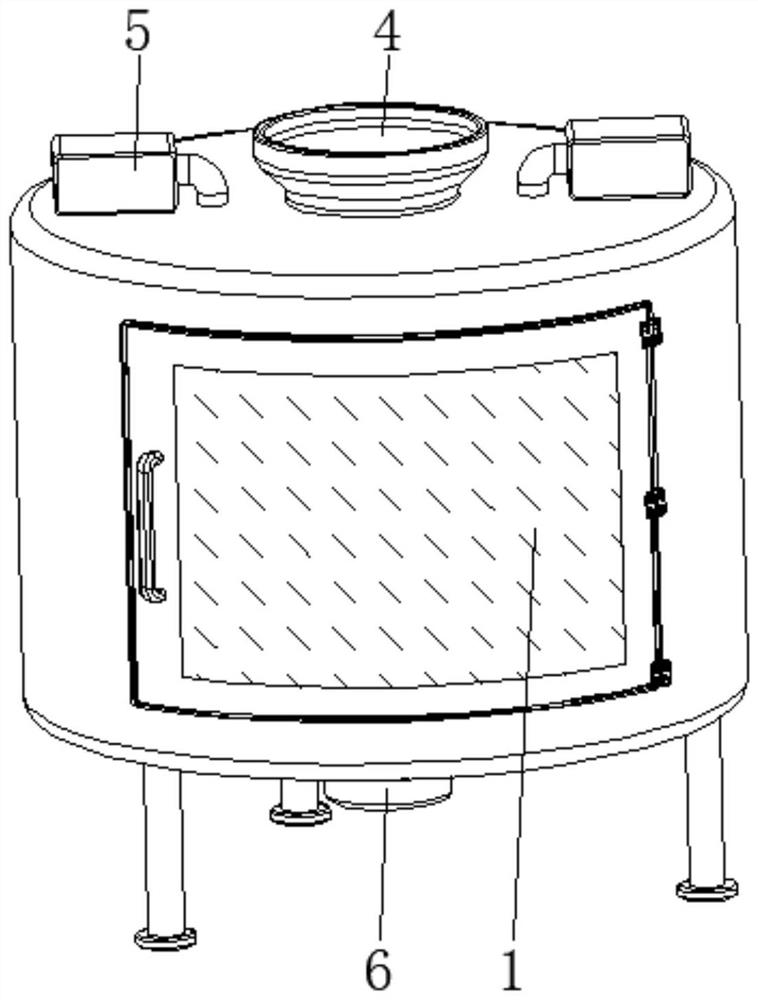
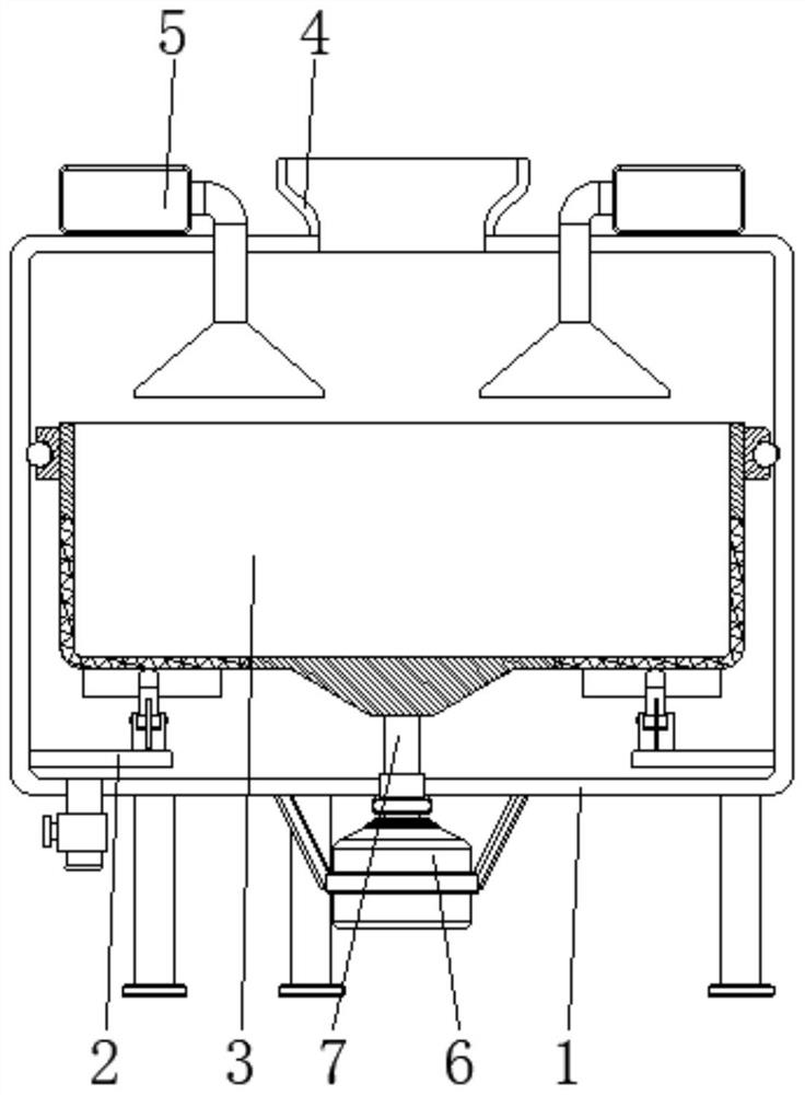
[0035] See Figure 1-6 The present invention provides a technical solution: an electronic component processing apparatus, including a body 1, a tap device 2, a storage device 3, and a tap device 2 are disposed in the inner wall of the body 1 and close to the bottom position, the storage device 3. The position provided inside the body 1 and close to the tap device 2;

[0036] The tap device 2 is evenly distributed in the inner wall of the body 1 and close to the bottom position, and the upper center position of the body 1 is provided with a feed strip 4, and both the top of the body 1 are provided with a hot fan 5, and the output of the hot air blower 5. The end through the top of the body 1 and extends to the interior of the body 1.

[0037] The center position of the bottom of the body 1 is fixed to the motor 6, and the output shaft of the motor 6 is mounted with the shaft 7, and the surface of the rotating shaft 7 is rotated between the bottom of the body 1, the top end of the ro...

Embodiment 2

[0039] The storage device 3 is provided with a storage base 31, an elastic leakage web 32, a blocking device 33, a loop body 34, a roller 35, and the storage base 31 are disposed in the internal center position of the body 1, and the elastic leakage network 32 is disposed in the storage group. The surface and bottom position of the bucket 31, the blocking device 33 is disposed at the bottom position of the elastic leakage web 32, and the roller body 34 is fixed to the top of the surface of the storage base 31, and the roller 35 rolls the interior of the circle body 34 and is located in the surface position. The surface of the roller 35 is rolled between the inner wall of the body 1, and when the rotation shaft 7 is rotated by the motor 6, the storage device 3 will rotate, and the material of the electronic component of the centrifugal force is attached. The position of the elastic leakage net 32, and the moisture of most of the surface of the raw material is removed, and the block...

Embodiment 3

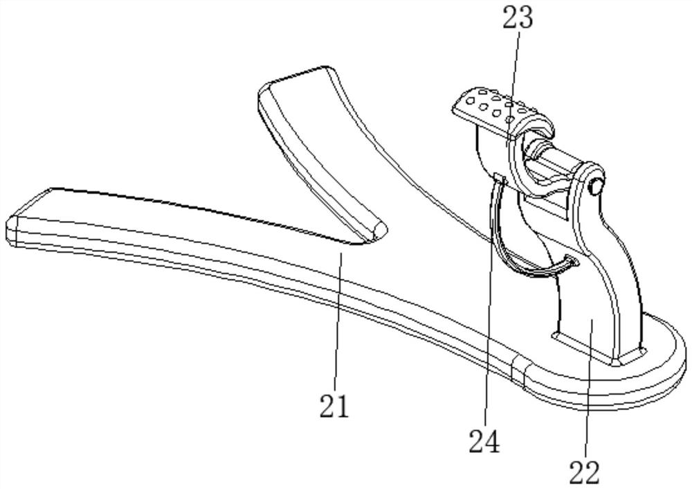
[0043] The tap device 2 is provided with a base 21, a curved strut 22, a hitting device 23, an arcuate ejection 24, and an inner wall of the base 21 and the inner wall of the body 1, and the curved surface strut 22 is fixed to the top of the base 21 and away from the inner wall of the body 1. At one end, the hitting device 23 is disposed at the top of the surface strut 22, and the arc-shaped ejection 24 is disposed between the surface of the hitting device 23 and the surface of the surface of the surface of the surface of the surface of the surface;

[0044] The hitting device 23 is provided with a support top moving member 231, an arc impact head 232, a ball 233, and a top end of the support top moving member 231 and the top of the surface of the surface of the surface of the surface of the curved head 232 fixed to the support top. The top of 231, the ball 233 rolls the inside of the curved impact head 232 and is located in the surface position, and when the barrier device 33 is ...


PUM


Abstract

The electronic component processing equipment comprises a machine body, a knocking device and a material storage device, the knocking device is arranged on the inner wall of the machine body and close to the bottom, the material storage device is arranged in the machine body and close to the knocking device, and a curved surface supporting column is fixed to the end, away from the inner wall of the machine body, of the top of a base. The striking device is arranged at the top of the curved-surface supporting column, the arc-shaped elastic piece is arranged between the two sides, corresponding to the surface of the curved-surface supporting column, of the surface of the striking device, the bottom end of the supporting and jacking piece is hinged to the top of the curved-surface supporting column, and the arc-surface striking head is fixed to the top end of the supporting and jacking piece. According to the electronic component processing equipment and method, the rapid drying effect is achieved, sheet parts are not prone to adhesion and accumulation, rapid and thorough drying can be conducted, follow-up use is facilitated, safety and reliability are achieved, and the working efficiency and the use performance are improved.

Description

Technical field [0001] The present invention relates to the technical field of electronic components processing equipment, and is specifically an electronic component processing apparatus and method. Background technique [0002] The electronic component is an electronic component and a small machine, the component of the instrument, which is often constructed of several parts, can be common in similar products; some parts of the electrical appliance, radio, instrumentation, etc., such as capacitors, transistors , The general name of submissions such as silk, hair strip. The history of electronic components is actually a history of concentrated electronics development. Electronic technology is the end of the 19th century, the emerging technology developed in the early 20th century, the trip to the twentieth century, the most widely used, and has become an important sign of modern science and technology development. During the processing of electronic components, the cleaning of c...

Claims


Application Information

Patent Timeline
IPC IPC(8): F26B5/08F26B11/18F26B21/00F26B25/00F26B25/04F26B25/18
Inventor 陈云
Owner 淮安市宝鼎科技有限公司
Why Eureka
Try Eureka