Capacitor level switch based on 555 time-base circuit

A level switch and circuit technology, applied in the direction of engine lubrication, instruments, machines/engines, etc., can solve problems such as inability to measure, narrow pulse width, and incapable of adaptive adjustment of materials with different dielectric constants, so as to avoid frequent adjustment. Inconvenient, moderate pulse width, best measurement results

Pending Publication Date: 2022-04-12
HUAIYIN INSTITUTE OF TECHNOLOGY
View PDF0 Cites 0 Cited by
  • Summary
  • Abstract
  • Description
  • Claims
  • Application Information

AI Technical Summary

Problems solved by technology

[0002] The PWM period of the existing capacitive level switch output to the trigger terminal of the 555 time base circuit is fixed. When measuring materials with low dielectric constant, such as petrochemical products, the pulse width of the output terminal of the 555 time base circuit is too narrow, so that the signal-to-noise ratio Low, difficult to measure; when measuring materials with high dielectric constant, such as salt water products, the pulse width of the output terminal of the 555 time base circuit is too wide, so that the signal exceeds the range and cannot be measured
Therefore, in the application, it is necessary to adjust the circuit parameters for different measured materials, and the adaptability of the measuring instrument is weak.
[0003] For non-conductive liquids, conductive liquids, iron powder and other materials with different dielectric constants, the capacitance C changes differently. The capacitance C of non-conductive liquids changes very little

Method used


Image

  • Capacitor level switch based on 555 time-base circuit
  • Capacitor level switch based on 555 time-base circuit
  • Capacitor level switch based on 555 time-base circuit

Examples


Example Embodiment

[0034] Example:

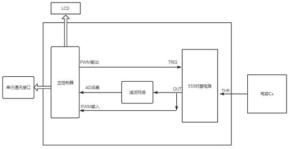
[0035] like figure 1 As shown, a capacitor level switch based on a 555 time base circuit includes a level capacitor CX and a controller module. The controller module includes a main controller, a voltage stabilizing circuit connected to the main controller and a serial Communication interface; the controller module also includes a 555 time base circuit, the input of the 555 time base circuit is connected to the level capacitor CX, and the output of the 555 time base circuit is connected to the AD of the main controller after passing through the π-type filter network circuit The acquisition terminal is connected, and the square wave output by the 555 time base circuit is filtered and then sent to the main controller. The main controller judges the height of the material level through the voltage value collected by the AD acquisition terminal; The trigger terminal of the base circuit is connected, and the output terminal of the 555 time base circuit is connect...


PUM


Abstract

The invention discloses a capacitance level switch based on a 555 time-base circuit, which comprises the 555 time-base circuit, the input end of the 555 time-base circuit is connected with a level tank body, capacitance formed by a measuring electrode and a tank body shell is in direct proportion to the height of the quantity, and the output end of the 555 time-base circuit is connected with the AD acquisition end of a main controller after passing through a pi-type filter network circuit; square waves output by the 555 time-base circuit are filtered and then transmitted to the main controller, and the main controller judges the height of the material level according to a voltage value collected by an AD end; the PWM output end of the main controller is connected with the trigger end of the 555 time-base circuit, and the output end of the 555 time-base circuit is connected with the main controller to form a closed loop; during debugging, the main controller outputs PWM with a large period to the trigger end of the 555 time-base circuit, collects the period and duty ratio of square waves output by the output end of the 555 time-base circuit under the condition that a material bin is full, and self-regulates the PWM output by the main controller to the trigger end of the 555 time-base circuit, so that the square waves output by the output end of the 555 time-base circuit reach the optimal signal-to-noise ratio of capacitance level switch measurement. According to the invention, the self-adaptive adjustment of the capacitance level switch on the measurement of materials with different dielectric constants is realized.

Description

technical field [0001] The invention relates to the technical field of material height measurement, in particular to a capacitive level switch based on a 555 time base circuit. Background technique [0002] The PWM period of the existing capacitive level switch output to the trigger terminal of the 555 time base circuit is fixed. When measuring materials with low dielectric constant, such as petrochemical products, the pulse width of the output terminal of the 555 time base circuit is too narrow, so that the signal-to-noise ratio Low, difficult to measure; when measuring materials with high dielectric constant, such as salt water products, the pulse width of the output terminal of the 555 time base circuit is too wide, so that the signal exceeds the range and cannot be measured. Therefore, in the application, it is necessary to adjust the circuit parameters for different measured materials, and the adaptability of the measuring instrument is weak. [0003] For non-conductiv...

Claims


Application Information

Patent Timeline
IPC IPC(8): G01F23/263
Inventor 刘虎赵俊杰陈明照路璐李烨吴俊黎尚哲唐圣辉
Owner HUAIYIN INSTITUTE OF TECHNOLOGY
Why Eureka
Try Eureka