Optical fiber introduction device and optical fiber introduction method

A technology of introducing devices and optical fibers, which is applied in the field of vacuum chambers, can solve problems such as affecting use, low airtightness, and leakage of workpiece table chambers, and achieves the effects of easy installation, high integration, and vacuum airtightness

Pending Publication Date: 2022-04-12
BEIJING U PRECISION TECH
View PDF0 Cites 1 Cited by
  • Summary
  • Abstract
  • Description
  • Claims
  • Application Information

AI Technical Summary

Problems solved by technology

One of the methods to realize the conduction of the optical fiber inside and outside the cavity is to use an integrated optical fiber to seal when passing through the wall of the vacuum cavity; the existing optical fiber introduction device, due to its low airtightness, will cause the cavity of the workpiece table to leak and affect the use

Method used


Image

  • Optical fiber introduction device and optical fiber introduction method
  • Optical fiber introduction device and optical fiber introduction method
  • Optical fiber introduction device and optical fiber introduction method

Examples


Embodiment Construction

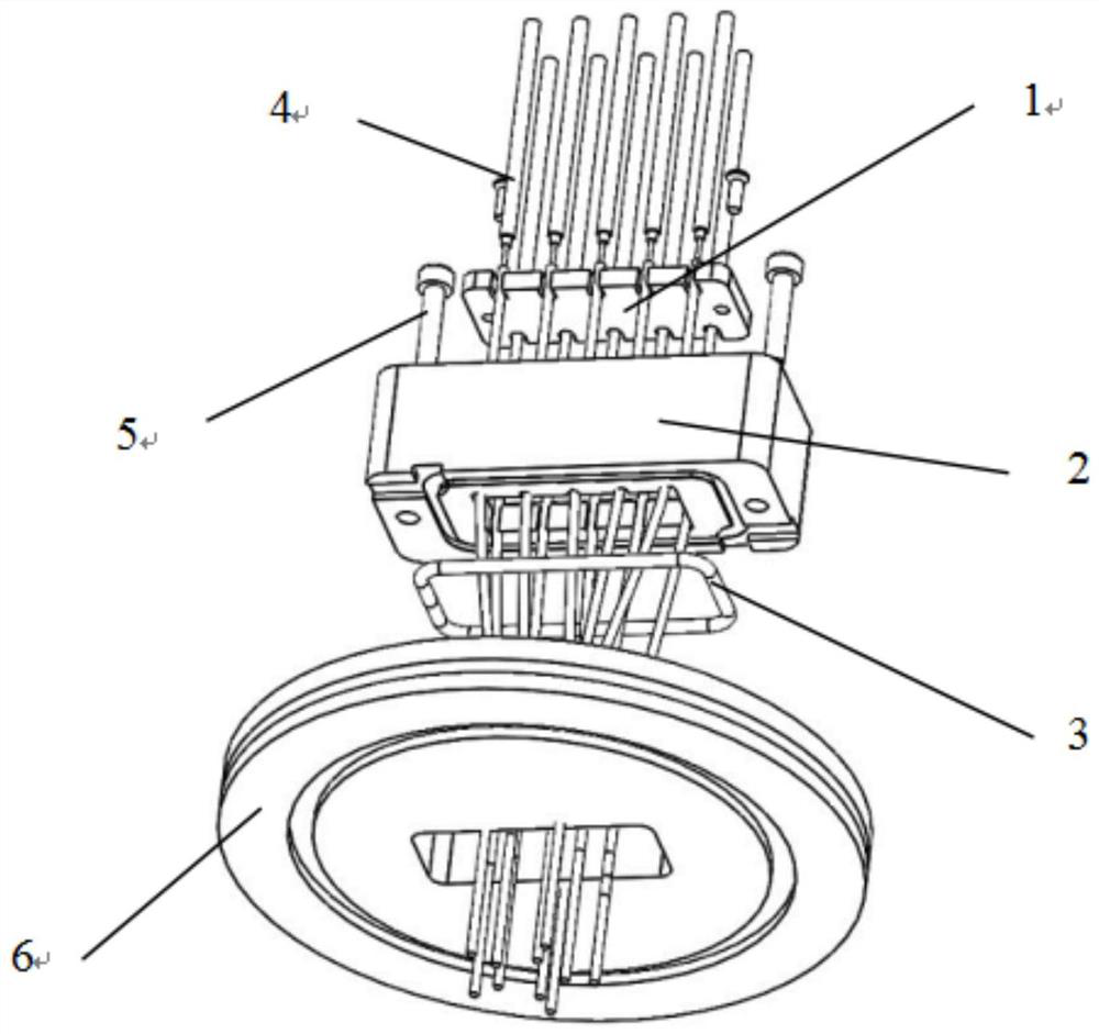
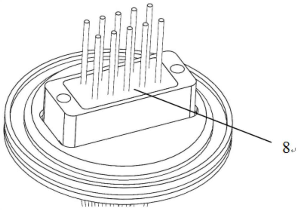
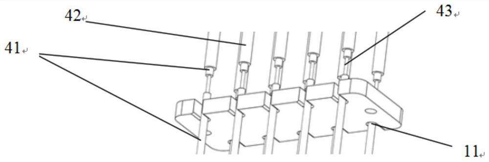
[0028] Such as figure 1 , figure 2 , image 3 , Figure 4 , Figure 5 As shown, an optical fiber introduction device according to an embodiment of the present invention includes a blocking piece 1, a glue filling seat 2, a vacuum potting glue layer, and a sealing and bonding glue layer 8. The metal material is processed, the block 1 is thin sheet, the edge of the block 1 is provided with a plurality of first grooves 11 for the optical fiber 4 to pass through, the glue filling seat 2 is a hollow body surrounded by side walls, A central hole 21 is formed in the center of the glue filling seat 2, and the inner wall of the glue filling seat 2 is provided with a first annular boss 24 and a second annular boss 27, and the width of the first annular boss 24 is greater than that of the second annular boss. The width of the table 27, the edge of the first annular boss 24 close to the central hole 21 is provided with a plurality of second grooves 22, the second grooves 22 are used ...


PUM


Abstract

The invention relates to the technical field of vacuum chambers, in particular to an optical fiber leading-in device and an optical fiber leading-in method for a vacuum chamber. The invention aims to provide an optical fiber leading-in device and an optical fiber leading-in method which are higher in air tightness when an optical fiber is led into a vacuum cavity. The optical fiber leading-in device comprises a blocking piece, a glue pouring seat, a vacuum pouring glue layer and a sealing bonding glue layer, a first groove body is formed in the edge of the blocking piece, a first annular boss and a second annular boss are arranged on the inner wall of the glue pouring seat, a second groove body is formed in the edge, close to a center hole, of the first annular boss, and a third groove body is formed in the edge, close to the center hole, of the second annular boss. The first groove body and the second groove body correspond to each other, the blocking piece is placed on the first annular boss, the blocking piece and the first annular boss are connected with each other, the first groove body and the second groove body which correspond to each other form a fixing groove used for containing a bare wire of one optical fiber, and the vacuum pouring sealant layer covers the blocking piece. And the sealing adhesive layer is covered on the vacuum pouring sealant layer.

Description

technical field [0001] The invention relates to the technical field of vacuum chambers, in particular to an optical fiber introduction device and an optical fiber introduction method for a vacuum chamber. Background technique [0002] At present, the propagation of extreme ultraviolet light in common EUV lithography machines requires a very high degree of vacuum in the workpiece table chamber. Considering the effects of outgassing and air tightness, part of the optical path needs to be transmitted through optical fibers inside and outside the chamber. One of the methods to realize the conduction of the optical fiber inside and outside the cavity is to use an integrated optical fiber to seal when passing through the wall of the vacuum cavity; the existing optical fiber introduction device, due to its low airtightness, will cause the cavity of the workpiece table to leak and affect the use . Contents of the invention [0003] The technical problem to be solved by the presen...

Claims


Application Information

Patent Timeline
Patent Type & Authority Applications(China)
IPC IPC(8): G02B7/00
CPCG02B7/00
Inventor 王妍智孙国华
Owner BEIJING U PRECISION TECH
Why Eureka
Try Eureka