
Feeder filter antenna and communication equipment

A filter antenna and feeder technology, which is applied in the field of feeder filter antenna and communication equipment, can solve the problems of unsatisfactory loss and radiation characteristics, high communication requirements, etc., and achieve the effects of wide processing cost, good radiation performance and wide application

Active Publication Date: 2022-07-12
SOUTH CHINA UNIV OF TECH +1
View PDF7 Cites 0 Cited by
  • Summary
  • Abstract
  • Description
  • Claims
  • Application Information

AI Technical Summary

Problems solved by technology

However, in the face of the current situation of limited product size and many communication frequency bands in the field of application terminals, the method has obvious defects, and the overall size, loss and radiation characteristics of the antenna cannot meet the increasingly high communication requirements.

Method used


Image

  • Feeder filter antenna and communication equipment
  • Feeder filter antenna and communication equipment
  • Feeder filter antenna and communication equipment

Examples


Embodiment 1

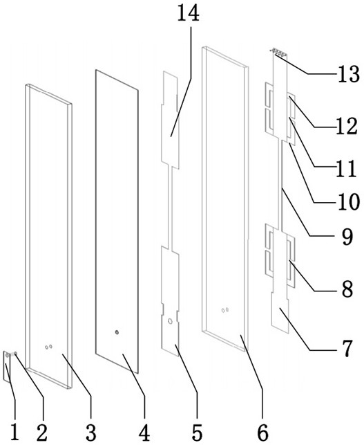
[0045] like Figure 1~Figure 3As shown, this embodiment provides a feeder filter antenna, which can be applied to a communication device, and the communication device can be a receiving and transmitting device of a wireless communication system. The antenna includes a feeder structure and a radiator structure. The feeder structure serves as the first First-order resonator, the radiator structure is loaded on the feeder structure, as the last-order resonator, together with the feeder structure to form a second-order filter, the radiation is realized by controlling the coupling between the first-order resonator and the last-order resonator The band-pass filtering effect of the bulk structure; since the feeder filter antenna of this embodiment is a second-order feeder filter antenna, the last-order resonator is the second-order resonator, and the resonance between the first-order resonator and the second-order resonator The characteristics are opposite.

[0046] In this embodime...

Embodiment 2

[0057] When implementing an N (N≥3) order feeder filter antenna, an additional resonator is coupled to the feeder filter antenna. The equivalent circuit diagram of the feeder filter antenna with N order resonance is shown in the figure. Figure 9a~Figure 9b shown.

[0058] This embodiment provides a third-order feeder filter antenna. A third-order filter network is constructed by using two-section feeders and a radiator structure in the form of a feeder as a resonator. The antenna equivalent circuit corresponds to Figure 9a~Figure 9b The filter network when N=3, such as Figure 10 As shown, this embodiment adds an additional parallel bifilar resonator 14 on the basis of Embodiment 1, the other structure is the same as that of Embodiment 1, and then introduces an additional first-order resonance into the antenna, and the parallel bifilar resonator 14 The top is open and the bottom is short-circuited to ground, which is equivalent to parallel resonance at the operating frequen...


PUM


Abstract

The invention discloses a feeder filter antenna and a communication device. The antenna includes a feeder structure and a radiator structure. The feeder structure serves as a first-order resonator, and the radiator structure is loaded on the feeder structure as a last-order resonator. The resonator, together with the feeder structure, forms a second-order filter, and realizes the band-pass filtering effect of the radiator structure by controlling the coupling between the first-order resonator and the last-order resonator; when the third-order or above feeder filter antenna is realized , an additional resonator is coupled to the second-order feed-line filter antenna. The invention can not only effectively filter out in-band and out-of-band interference, but also the return loss and efficiency of the antenna change little compared with the single antenna, and can ensure the horizontal direction radiation and gain requirements of the vehicle-mounted antenna.

Description

technical field [0001] The invention relates to a feeder filter antenna and communication equipment, and belongs to the research field of multi-frequency base station antennas in the aspect of wireless mobile communication. Background technique [0002] In recent years, with the rapid development of modern wireless communication systems, more and more frequency bands are required for mobile communication, resulting in the strong mutual coupling between antenna elements when antennas of different frequency bands coexist in a small space, resulting in the performance of the antenna. deteriorating and further deteriorating the performance of the wireless communication system. [0003] For example, in the current era of Internet of Vehicles, the Internet of Vehicles antenna in the vehicle antenna system is integrated with satellite navigation antennas, 2G / 3G / 4G / 5G antennas, etc. This leads to the existence of a large number of antennas operating in different frequency bands in ...

Claims


Application Information

Patent Timeline
Patent Type & Authority Patents(China)
IPC IPC(8): H01Q1/36H01Q15/00H01Q1/50
CPCY02D30/70H01Q1/36H01Q1/50H01Q15/00
Inventor 章秀银吴琳玲徐慧梁苏华峰
Owner SOUTH CHINA UNIV OF TECH
Learn More