
Motor rotor, motor, and production equipment and process of motor rotor

A motor rotor and production process technology, applied in metal processing equipment, grinding/polishing equipment, manufacturing stator/rotor body, etc., can solve the problem of low utilization rate of polishing equipment, waste of production resources, affecting the quality of motor rotors, and affecting the work of motor rotors and other issues to achieve the effect of improving adaptability and utilization, ensuring polishing effect, and saving production resources

Active Publication Date: 2022-04-12
江苏恒驰电机科技有限公司
View PDF13 Cites 0 Cited by
  • Summary
  • Abstract
  • Description
  • Claims
  • Application Information

AI Technical Summary

Problems solved by technology

[0003] The smoothness of the rotor core slot will affect the quality of the motor rotor. It is necessary to polish the rotor core slot after production. However, the rotor iron required in different situations The number of core grooves may vary. Generally, the number of rotor core grooves is fixed. During polishing, different polishing equipment needs to be replaced for production and processing, resulting in a low utilization rate of polishing equipment and a waste of production resources. When polishing, it is difficult for the polishing equipment to always stick to the groove surface of the rotor iron core groove, resulting in poor polishing effect and affecting the work of the motor rotor

Method used


Image

  • Motor rotor, motor, and production equipment and process of motor rotor
  • Motor rotor, motor, and production equipment and process of motor rotor
  • Motor rotor, motor, and production equipment and process of motor rotor

Examples


Embodiment Construction

[0032] The embodiments of the present invention will be described in detail below with reference to the accompanying drawings, but the present invention can be implemented in many different ways defined and covered by the claims.

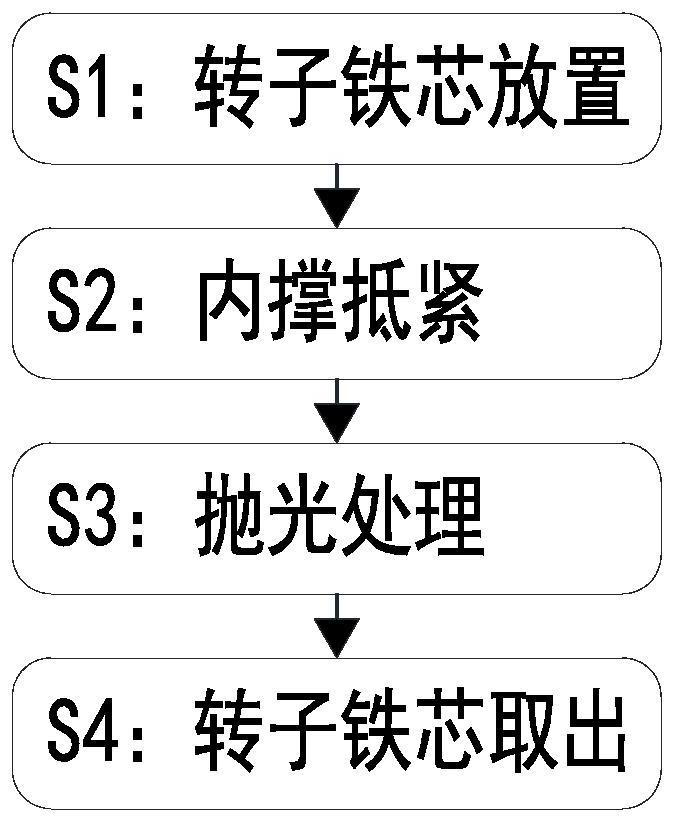
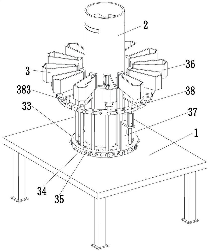
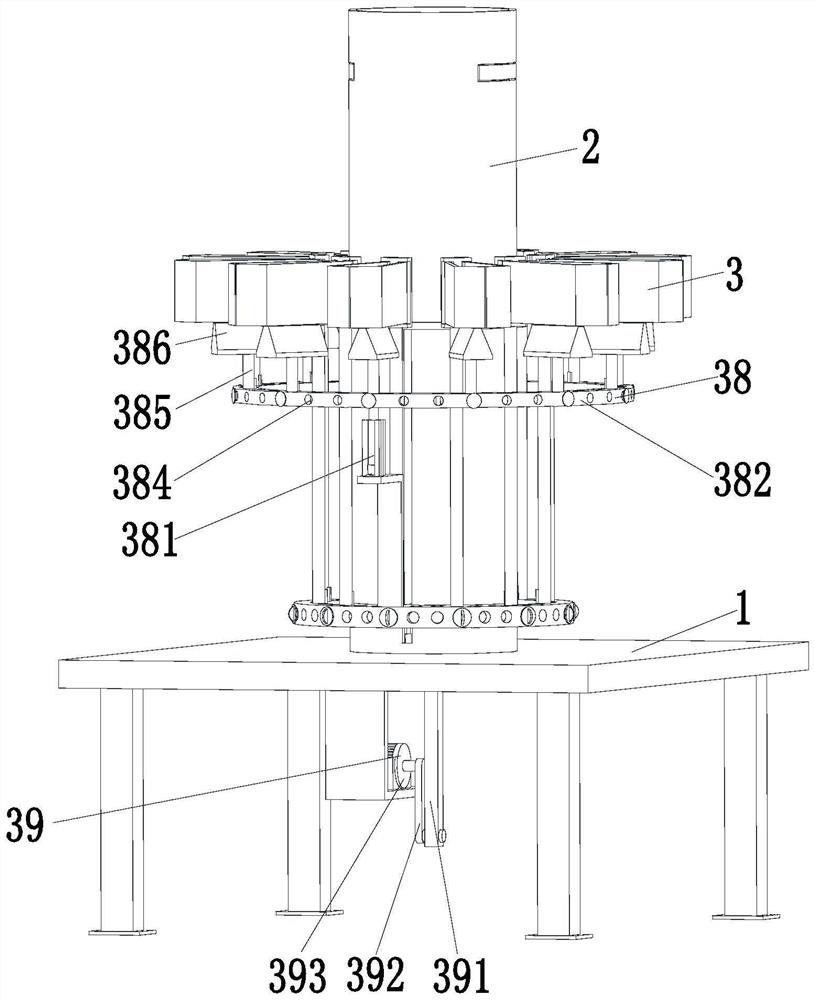
[0033] refer to figure 1 , figure 2 , image 3 , Figure 4 with Image 6 , a production process of a motor rotor, which uses a production equipment of a motor rotor, the equipment includes a workbench 1, a cylinder 2, a polishing device 3 and a support ring 4, and the middle part of the workbench 1 is provided with a circular Through groove, a cylinder 2 is installed on the circular through groove, a polishing device 3 is arranged on the cylinder 2, a support ring 4 is installed on the outer wall of the cylinder 2, and a symmetrical stop rod is installed on the upper side of the cylinder 2 for sliding 21. There is a two-way cylinder 22 connected between the stop rods 21. The middle part of the two-way cylinder 22 is fixed in the cylinder body 2...


PUM


Abstract

The invention relates to the technical field of motor production, in particular to a motor rotor, a motor and production equipment and process of the motor rotor, the equipment comprises a workbench, a cylinder, a polishing device and a supporting ring, a circular through groove is formed in the middle of the workbench, the cylinder is installed on the circular through groove, the polishing device is arranged on the cylinder, and the supporting ring is arranged on the cylinder. A supporting ring is installed on the outer wall of the barrel. Compared with the prior art, the rotor core with the variable rotor core groove number is designed, the rotor core requirements under different conditions are met, meanwhile, the production equipment of the motor rotor is further provided, polishing treatment can be conducted on the rotor cores with different groove numbers, the adaptability and the utilization rate of the equipment are improved, production resources are saved, and the production cost is reduced. And the polishing plate can be always clung to the inner wall of the rotor iron core groove in the polishing process, so that the polishing effect on the rotor iron core is ensured.

Description

technical field [0001] The invention relates to the technical field of motor production, in particular to a motor rotor, a motor, and production equipment and technology for the motor rotor. Background technique [0002] The motor refers to an electromagnetic device that realizes the conversion or transmission of electric energy according to the law of electromagnetic induction. The motor is generally composed of two parts: the rotor and the stator. The rotor part is connected to the driven equipment through the shaft. The rotor is generally composed of a shaft, a bearing, a rotor fan, and a rotor core, among which the rotor core is a component that supports the rotor guide bar. Among them, the smoothness of the core groove and the springing of the end are very important, otherwise the rotor winding will be damaged. Wire embedding is difficult or unnecessary electrical failure occurs. [0003] The smoothness of the rotor core slot will affect the quality of the motor rotor....

Claims


Application Information

Patent Timeline
Patent Type & Authority Applications(China)
IPC IPC(8): H02K15/02B24B21/16
Inventor 刘先起高明真
Owner 江苏恒驰电机科技有限公司
Learn More