Eureka AIR delivers breakthrough ideas for toughest innovation challenges, trusted by R&D personnel around the world.

Road engineering detection device based on BIM

A detection device and road engineering technology, which is applied to circuit devices, battery circuit devices, roads, etc., can solve the problems of reducing the storage space of road engineering detection devices, inconvenient transportation of road engineering detection devices, and large size of road engineering detection devices. Improve power supply efficiency, facilitate storage, and improve utilization

Pending Publication Date: 2022-04-15
刘遥峰
View PDF10 Cites 0 Cited by
  • Summary
  • Abstract
  • Description
  • Claims
  • Application Information

AI Technical Summary

Problems solved by technology

[0006] The invention provides a BIM-based road engineering detection device, one of the purposes of which is to facilitate the retraction of the road engineering detection device, reduce the storage space of the BIM road engineering detection device, and facilitate the transportation of the BIM road engineering detection device The purpose is to solve the problem that the BIM road engineering detection device is large in size, thus greatly improving the storage space of the BIM road engineering detection device, and it is not convenient to transport the BIM road engineering detection device; another purpose is to solve the problem of BIM The road engineering detection device of BIM needs to consume a lot of energy during work, which causes the problem of waste of non-renewable resources, so as to achieve the effect of making BIM's road engineering detection device energy-saving and environmentally friendly, and reduce the consumption of non-renewable resources

Method used

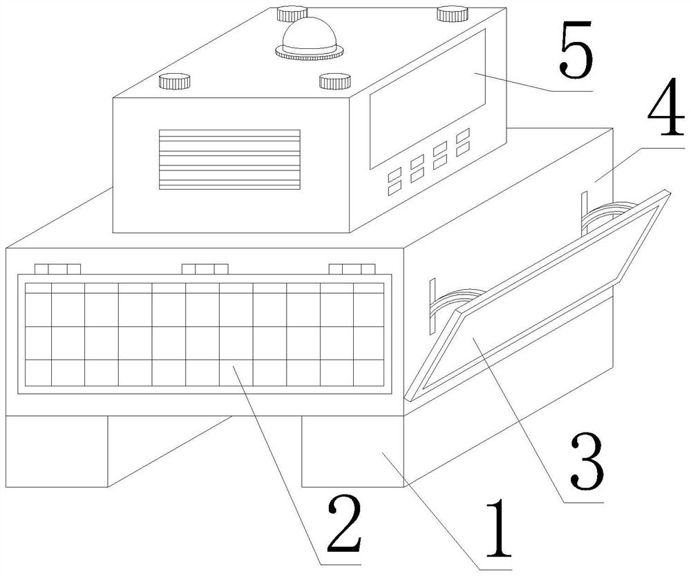

Image

  • Road engineering detection device based on BIM
  • Road engineering detection device based on BIM
  • Road engineering detection device based on BIM

Examples


Embodiment 1

[0041] Such as Figure 1-6 As shown, the present invention provides a road engineering detection device based on BIM, comprising a detection box 4, a controller main body 5 is fixedly installed on the top of the detection box 4, a mobile device 1 is fixedly installed on the bottom of the detection box 4, and the detection box The front of the body 4 is provided with a detection device 3, and the left and right sides of the detection box body 4 are fixedly installed with an energy-saving device 2. The energy-saving device 2 includes a bracket box 21, and the right side of the bracket box 21 is fixedly installed with one side of the detection box body 4 The left side of the bracket box 21 is connected with a solar panel 22 for rotation, and the detection device 3 includes a BIM road detector bracket box 31, the outer wall of the BIM road detector bracket box 31 is fixedly installed with the front of the detection box body 4, and the BIM road detector bracket box The right end of...

Embodiment 2

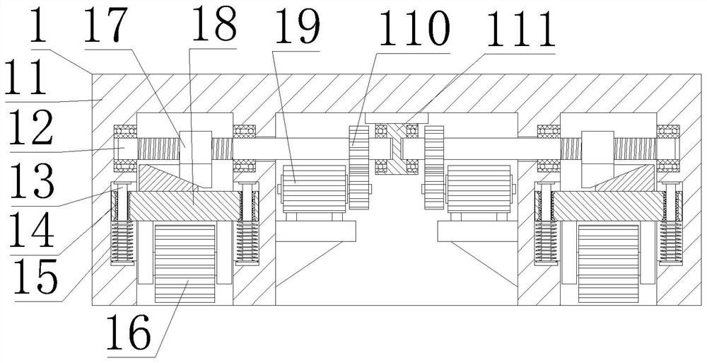
[0044] Such as Figure 1-6 As shown, on the basis of Embodiment 1, the present invention provides a technical solution: preferably, the mobile device 1 includes an outrigger box 11, the top of the outrigger box 11 is fixedly installed with the bottom of the detection box 4, and the outrigger box 11. A support block 111 is fixedly mounted on the top of the inner chamber, and the left and right sides of the support block 111 are rotatably connected with a threaded transmission shaft 12. One end of the outer wall of the threaded transmission shaft 12 is fixedly equipped with a gear set 110, and the bottom of the left side of the gear set 110 is provided with Transmission motor 19, the other end of screw drive shaft 12 outer wall is threadedly connected with internal thread slanting block 17, and the bottom of internal thread slanting block 17 is provided with guide support plate 18, and the bottom of guide support plate 18 is provided with rotation non-slip moving wheel 16, guides...

Embodiment 3

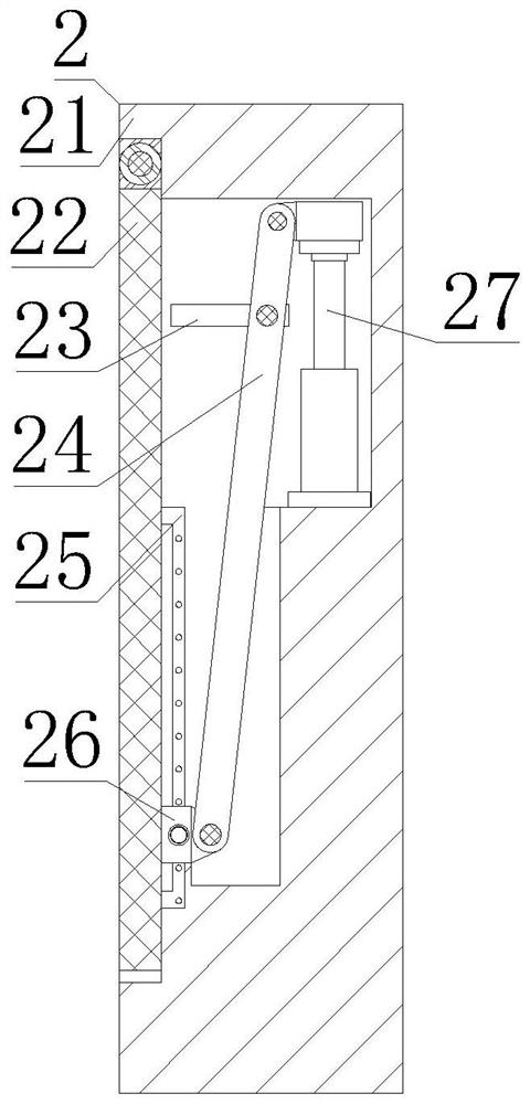
[0047] Such as Figure 1-6 As shown, on the basis of Embodiment 1, the present invention provides a technical solution: preferably, the right end of the inner cavity of the bracket box 21 is fixedly equipped with a hydraulic rod 27, and the left side of the top of the hydraulic rod 27 is rotationally connected with a strut 24, The bottom of pole 24 is rotatably connected with adjustment slider 26, the inner wall of adjustment slider 26 is slidably connected with slide rail 25, and the back side of bracket box 21 is slidably connected with chute 23, and adjustment slider 26 includes adjustment slider main body 261. The inner wall of the slider main body 261 is slidingly connected with the outer wall of the slide rail 25, and the left side of the outer wall of the adjustment slider main body 261 is rotatably connected with an adjustment nut 262, and the right end of the adjustment nut 262 is fixedly installed with a threaded sleeve on the front side of the adjustment slider main ...


PUM


Abstract

The invention discloses a BIM-based road engineering detection device, and relates to the technical field of engineering detection devices.The BIM-based road engineering detection device comprises a detection box body, a controller body is fixedly mounted at the top of the detection box body, a moving device is fixedly mounted at the bottom of the detection box body, and a detection device is arranged on the front face of the detection box body. According to the road engineering detection device disclosed by the invention, under the action of a transmission motor, a gear set rotates, so that a threaded transmission shaft rotates, an internal threaded inclined block moves, and the height of a rotary anti-skid moving wheel is adjusted, so that the purpose of stretching and retracting the rotary anti-skid moving wheel is achieved, and the road engineering detection device is convenient to move; under the action of a guide column, a guide supporting plate is fixed, the problem that a rotating anti-skid moving wheel swings during rotation is solved, under the action of a reset spring, the rotating anti-skid moving wheel is conveniently contracted, the road engineering detection device is prevented from moving during storage, and the road engineering detection device is conveniently stored.

Description

technical field [0001] The invention relates to the technical field of engineering detection devices, in particular to a BIM-based road engineering detection device. Background technique [0002] Road engineering includes road trench excavation and filling processes. Road trench excavation is based on road design, and all soil above the design level on the road section to be constructed is excavated to form a road bed. Filling is to lay three layers of cement on the road bed in sequence. Stone, modified emulsified asphalt slurry seal, coarse-grained asphalt mixture, medium-grained asphalt mixture and fine-grained asphalt mixture, in the construction process, in order to ensure the quality and beauty of the road, it is necessary to use BIM road engineering The detection device is used to detect the depth of the road bed and the height of each layer of filler to ensure that the road is qualified after laying. [0003] There are following problems at prior art: [0004] 1. Th...

Claims


Application Information

Patent Timeline
Patent Type & Authority Applications(China)
IPC IPC(8): E01C23/01H02S20/30H02S30/20H02J7/35
CPCY02E10/50
Inventor 刘遥峰
Owner 刘遥峰
Why Eureka
Eureka Blog
Learn More