Coaxial automatic diameter adjusting mechanical device for mechanical equipment
A technology of mechanical equipment and mechanical devices, which is applied in the field of automatic diameter-adjusting mechanical devices, can solve the problems of unstable diameter-adjusting rotation of movable shafts, low working efficiency of devices, and inability to work stably, so as to improve stability, resist pressure, and improve work efficiency. Efficiency, solution to unstable effects
- Summary
- Abstract
- Description
- Claims
- Application Information
AI Technical Summary
Problems solved by technology
Method used
Image
Examples
Embodiment 1
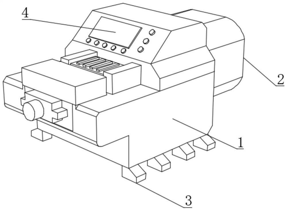
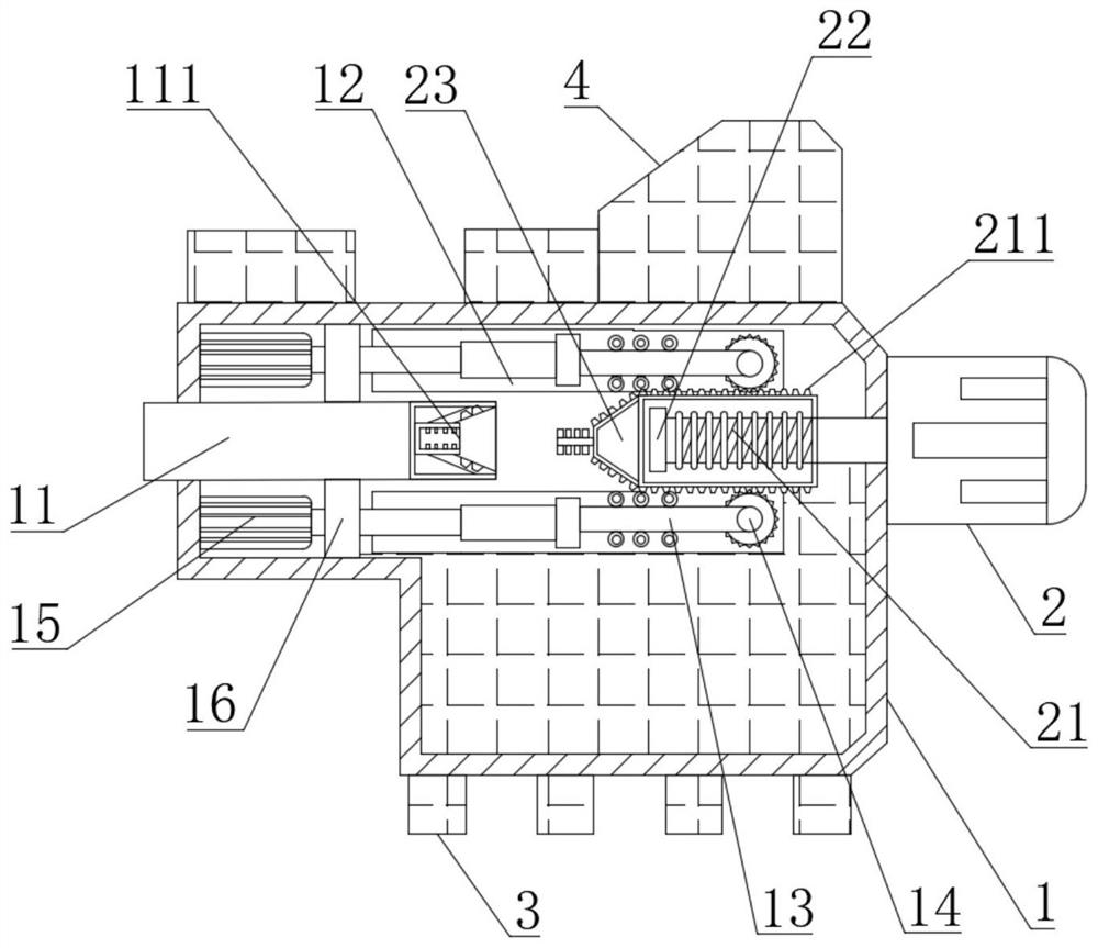
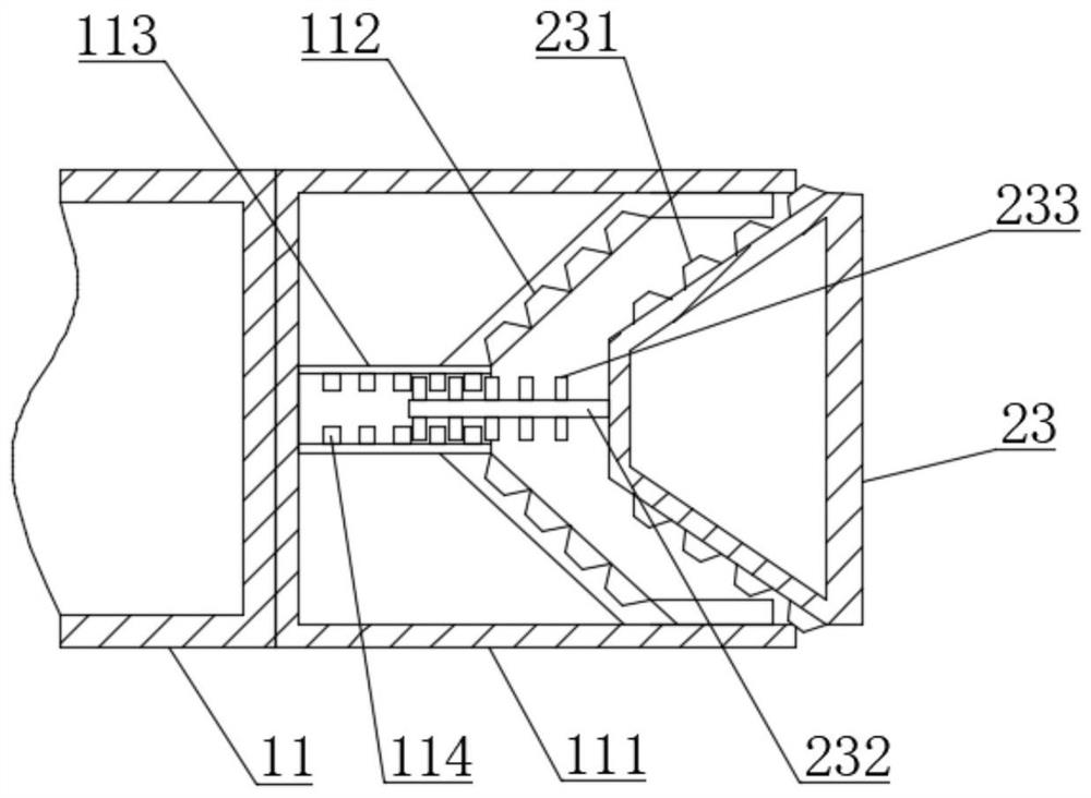
[0045] Such as Figure 1-6As shown, the present invention provides a coaxial automatic diameter adjustment mechanical device for mechanical equipment, including a device body 1, a drive motor 2 is fixedly connected to one side of the device body 1, and a foot 3 is fixedly installed on the bottom of the device body 1. The outer surface of the body 1 is fixedly connected with the control panel 4, the output shaft of the drive motor 2 extends to the inside of the device body 1, the outer surface of the output shaft of the drive motor 2 is movably connected with a threaded sleeve 21, and the outer surface of the threaded sleeve 21 is fixedly connected with a The outer rack 211, one end of the output shaft of the drive motor 2 is fixedly connected with the first limit block 22, the inside of the device body 1 is provided with a movable shaft 11, and one end of the movable shaft 11 extends to the outside of the device body 1, and the device body 1 Both sides of the inner wall are pr...
Embodiment 2
[0048] Such as Figure 1-6 As shown, on the basis of Embodiment 1, the present invention provides a technical solution: preferably, the inner surface of the fixed plate 16 is fixedly connected with a spring 161, and one end of the spring 161 is fixedly connected with a shock absorber 162, and the shock absorber 162 The outer surface is fixedly connected with a rubber pad 163, the inner surface of the shock absorber 162 is fixedly connected with a connecting shaft 1621, one end of the connecting shaft 1621 extends to the inside of the shock absorbing block 162, and the two ends of the connecting shaft 1621 are fixedly connected with a third stop Block 1622, the outer surface of the third limiting block 1622 is movably connected with a ball 1623, and both ends of the inner surface of the shock absorbing block 162 are fixedly connected with protrusions 1624.
[0049] In this embodiment, the fixed plate 16 provides support during the rotation of the movable shaft 11 to improve the...
Embodiment 3
[0051] Such as Figure 1-6 As shown, on the basis of Embodiment 1, the present invention provides a technical solution: preferably, one side of the inner surface of the movable shaft 11 is fixedly connected with a limiting cylinder 113, and the inner surface of the limiting cylinder 113 is fixedly connected with a second limiting cylinder. The position block 114, the second limit block 114 is compatible with the clamping block 233, the outer surface of the slide rod 13 is movably connected with a pulley 131, and the end of the slide rod 13 away from the gear 14 is fixedly connected with a second sleeve 132, the second sleeve 132 A T-shaped block 133 is arranged inside, one end of the T-shaped block 133 is fixedly connected with the telescopic rod 15 , and a buffer airbag 134 is fixedly connected with one side of the inner wall of the second sleeve 132 .
[0052] In this embodiment, the conical head 23 clamps the extension end 232 to the inside of the limiting cylinder 113, so ...
PUM
 Abstract
Description
Claims
Application Information
 - R&D
- Intellectual Property
- Life Sciences
- Materials
- Tech Scout
- Unparalleled Data Quality
- Higher Quality Content
- 60% Fewer Hallucinations
Browse by: Latest US Patents, China's latest patents, Technical Efficacy Thesaurus, Application Domain, Technology Topic, Popular Technical Reports.
© 2025 PatSnap. All rights reserved.Legal|Privacy policy|Modern Slavery Act Transparency Statement|Sitemap|About US| Contact US: help@patsnap.com


