
Manufacturing method of damping backing of ultrasonic probe

A technology of an ultrasonic probe and a manufacturing method, which is applied in the direction of material analysis, measurement device, and instrument using sonic/ultrasonic/infrasonic waves, can solve the problems of low controllability of sound absorption parameters, reduced attenuation effect, and difficult process control, etc. Reduced effects of process instabilities, reduced backing thickness, easy-to-achieve effects

Pending Publication Date: 2022-04-15
CHINA SPECIAL EQUIP INSPECTION & RES INST
View PDF0 Cites 0 Cited by
  • Summary
  • Abstract
  • Description
  • Claims
  • Application Information

AI Technical Summary

Problems solved by technology

However, this method has the following problems: 1. The particle size and dispersion of the tungsten powder have a great influence on the actual sound absorption effect. The tungsten powder is easy to gather into agglomerates or settle at the bottom, which seriously reduces the attenuation effect. The process is difficult to control. High requirements for production personnel's operation and experience; 2. The formulation of tungsten powder particle size and concentration is completely based on experience, and there is no empirical formula corresponding to the target attenuation frequency band, and there is no clear relationship with the probe design center frequency, bandwidth and other parameters. 3. Since the lower the ultrasonic frequency, the smaller the attenuation in the material, so for this method, the sound absorption or damping effect is not good for the lower frequency ultrasonic probe, or To obtain the attenuation effect, so that the sound wave needs a longer distance to increase the thickness of the backing, thereby increasing the size and weight of the probe
In summary, the existing backing material manufacturing methods have problems such as poor process stability, low controllability of sound absorption parameters, and difficulty in guaranteeing low-frequency effects.

Method used


Image

  • Manufacturing method of damping backing of ultrasonic probe
  • Manufacturing method of damping backing of ultrasonic probe
  • Manufacturing method of damping backing of ultrasonic probe

Examples


Embodiment Construction

[0033] The technical solution of the present invention will be described in detail below in conjunction with the accompanying drawings and specific embodiments.

[0034] The invention aims to solve the problem of uncontrollable sound-absorbing frequency and bandwidth of the damping backing of the ultrasonic probe and the problem of poor damping effect, and proposes a manufacturing method of the damping backing of the ultrasonic probe.

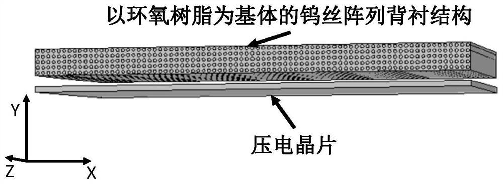
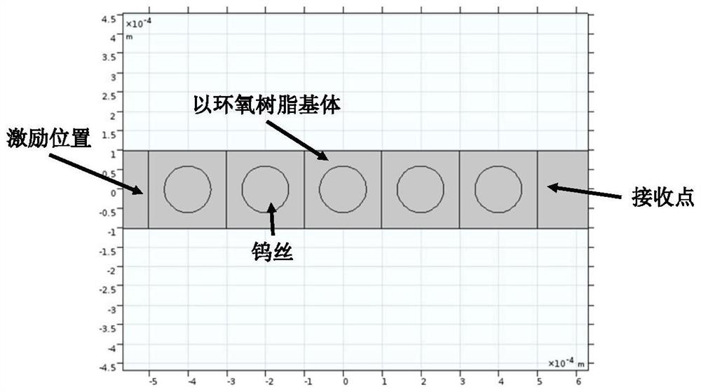
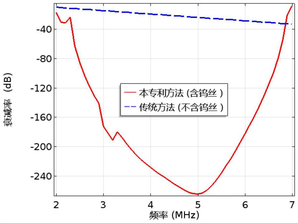
[0035] Taking the commonly used linear array ultrasonic probe with a center frequency of 5 MHz, a bandwidth of 60%, and 32 array elements as an example, its size is 16 mm×10 mm. Taking tungsten wire as an example, according to the formula (1), the distance a=0.2mm is calculated, and the diameter of the tungsten wire d≥0.112mm. In this embodiment, the diameter d is taken as 0.12mm, and the thickness of the backing is taken as 5 times the distance, that is, 1mm . The resulting backing and its installation on the piezoelectric chip are shown in ...


PUM

PropertyMeasurementUnit
diameteraaaaaaaaaa
thicknessaaaaaaaaaa

Abstract

The invention relates to a method for manufacturing a damping backing of an ultrasonic probe. The method comprises the following steps: 1) determining the center frequency fc and the bandwidth delta f of the probe; 2) determining a distance a according to the center frequency of the probe, and determining the diameter d of the metal wire according to the bandwidth; (3) the metal wires are arranged in the two-dimensional XOY direction at the interval of a, the axial direction of the metal wires is in the Z direction, and epoxy resin is poured for forming; and 4) cutting the resin block according to the size and the shape of the probe, and mounting the resin block on the back surface of the piezoelectric wafer as a backing. Wherein the plane where the piezoelectric wafer is located is along an XOZ plane or a YOZ plane. The method is convenient to manufacture, and the wave absorbing frequency and the bandwidth of the manufactured damping backing of the ultrasonic probe are convenient to adjust.

Description

technical field [0001] The invention relates to the field of ultrasonic detection, in particular to a method for manufacturing an ultrasonic probe damping backing. Background technique [0002] In the structure of the ultrasonic probe, one of the main functions of the piezoelectric wafer backing material is to absorb the sound wave radiated from the back of the piezoelectric wafer. Otherwise, the sound wave will be received by the piezoelectric wafer after reflection, and may even penetrate into the workpiece, thereby affect the test results. At present, the backing material is mostly made of epoxy resin. The production method is to add tungsten powder and other substances to the epoxy resin according to experience to increase the attenuation of the backing to the sound wave. However, this method has the following problems: 1. The particle size and dispersion of the tungsten powder have a great influence on the actual sound absorption effect. The tungsten powder is easy to ...

Claims


Application Information

Patent Timeline
Patent Type & Authority Applications(China)
IPC IPC(8): G01N29/24B29C69/00
Inventor 张驰潘强华郑晖刘太丽
Owner CHINA SPECIAL EQUIP INSPECTION & RES INST
Learn More