
Cable intermediate joint detection device

A technology of cable intermediate joint and detection device, which is applied in the direction of measuring device, electrical connection test, measuring device shell, etc., can solve the problems of unqualified crimping quality, high heat generation, damage to copper connecting pipe cable insulation, etc.

Pending Publication Date: 2022-04-15
JIAOZUO POWER SUPPLY COMPANY OF STATE GRID HENAN ELECTRIC POWER
View PDF0 Cites 0 Cited by
  • Summary
  • Abstract
  • Description
  • Claims
  • Application Information

AI Technical Summary

Problems solved by technology

[0002] Cable is a kind of electric energy or signal transmission device, usually composed of several or several groups of wires, in order to facilitate cable laying in practical application installation, segmented cables are used, and the segmented cables are connected into a whole by using intermediate joints For cables, due to inadequate construction management and weak skills of operators, the crimping quality of cable intermediate joints during construction is unqualified, and the production process of cable intermediate joints is not strictly installed for crimping. There is a phenomenon of virtual pressure, which may easily cause contact resistance at cable intermediate joints Excessively large, high heat generation and high temperature will damage the insulation of the copper connecting pipe and the cables at both ends, and even burn the copper connecting pipe or burn the cable at the joint; therefore, to provide a simple structure, convenient installation, on-line monitoring, It is very necessary to have an automatic alarm cable middle joint detection device

Method used


Image

  • Cable intermediate joint detection device
  • Cable intermediate joint detection device
  • Cable intermediate joint detection device

Examples


Embodiment 1

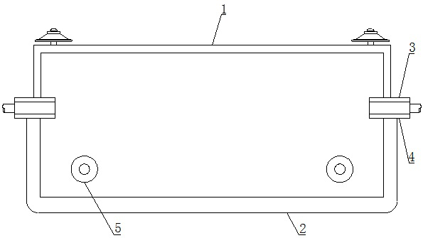
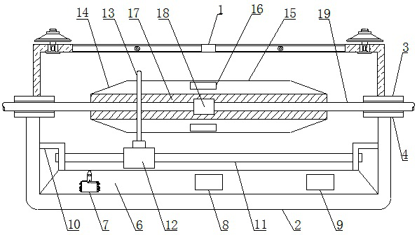
[0027] Such as Figure 1-9 As shown, the cable intermediate joint detection device includes an upper cover body 1 and a lower cover body 2, upper fixing plates 3 are arranged on the left and right sides below the upper cover body 1, and upper fixing plates 3 are arranged on the lower side of the upper cover body 1. The lower cover 2, the upper left and right sides of the lower cover 2 are provided with lower fixing plates 4, the front left and right sides of the lower cover 2 are provided with alarm components 5, and the lower part of the alarm component 5 is provided with There is a base plate 39, an alarm 40 is arranged above the base plate 39, a base 6 is arranged below the inside of the lower cover 2, and a transmitter 7 and a collector are arranged in sequence from left to right inside the base 6. 8 and the processor 9, brackets 10 are provided on the left and right sides above the base 6, a slide bar 11 is provided inside the support 10, and a slide seat 12 is provided o...

Embodiment 2

[0033] Such as Figure 1-9 As shown, the cable intermediate joint detection device includes an upper cover body 1 and a lower cover body 2, upper fixing plates 3 are arranged on the left and right sides below the upper cover body 1, and upper fixing plates 3 are arranged on the lower side of the upper cover body 1. The lower cover 2, the upper left and right sides of the lower cover 2 are provided with lower fixing plates 4, the front left and right sides of the lower cover 2 are provided with alarm components 5, and the lower part of the alarm component 5 is provided with There is a base plate 39, an alarm 40 is arranged above the base plate 39, a base 6 is arranged below the inside of the lower cover 2, and a transmitter 7 and a collector are arranged in sequence from left to right inside the base 6. 8 and the processor 9, brackets 10 are provided on the left and right sides above the base 6, a slide bar 11 is provided inside the support 10, and a slide seat 12 is provided o...


PUM


Abstract

The invention relates to a cable intermediate joint detection device which comprises an upper cover body and a lower cover body, upper fixing plates are arranged on the left side and the right side below the upper cover body, the lower cover body is arranged below the upper cover body, lower fixing plates are arranged on the left side and the right side above the lower cover body, alarm assemblies are arranged on the left side and the right side of the front face of the lower cover body, and a base is arranged on the lower portion in the lower cover body. The transmitter, the collector and the processor are sequentially arranged in the base from left to right, the supports are arranged on the left side and the right side above the base, the sliding rods are arranged on the inner sides of the supports, the sliding bases are arranged outside the sliding rods, the temperature measuring rings are arranged above the sliding bases, the intermediate connector body is arranged in the temperature measuring rings, and the shielding shell is arranged outside the intermediate connector body. Antennae are arranged on the upper side and the lower side in the shielding shell, insulating layers are arranged on the inner sides of the antennae, first temperature sensors are arranged in the insulating layers, and cables are arranged in the first temperature sensors; the device has the advantages of simple structure, convenience in installation, online monitoring and automatic alarm.

Description

technical field [0001] The invention belongs to the technical field of cable intermediate joint appliances, and in particular relates to a cable intermediate joint detection device. Background technique [0002] Cable is a kind of electric energy or signal transmission device, usually composed of several or several groups of wires, in order to facilitate cable laying in practical application installation, segmented cables are used, and the segmented cables are connected into a whole by using intermediate joints For cables, due to inadequate construction management and weak skills of operators, the crimping quality of cable intermediate joints during construction is unqualified, and the production process of cable intermediate joints is not strictly installed for crimping. There is a phenomenon of virtual pressure, which may easily cause contact resistance at cable intermediate joints Excessively large, high heat generation and high temperature will damage the insulation of t...

Claims


Application Information

Patent Timeline
Patent Type & Authority Applications(China)
IPC IPC(8): G01R1/04G01R31/69G01K13/00
Inventor 闫林凤杨贵营郭楠连庆喜王海港鲁华强刘慧杰张穹李笑冬刘涛
Owner JIAOZUO POWER SUPPLY COMPANY OF STATE GRID HENAN ELECTRIC POWER
Learn More