
Multi-particle-size filler filling type composite material fluidity simulation method

A composite material and simulation method technology, applied in the field of polymer composite material design, can solve the problem of not yet developed a high-efficiency calculation scheme, few three-particle size filling systems, etc.

Pending Publication Date: 2022-04-15
SHENZHEN INST OF ADVANCED TECH CHINESE ACAD OF SCI
View PDF0 Cites 1 Cited by
  • Summary
  • Abstract
  • Description
  • Claims
  • Application Information

AI Technical Summary

Problems solved by technology

[0004] After analysis, the existing simulation methods are generally aimed at single particle size filling systems or single particle size filling systems considering particle size distribution, and few studies are aimed at three particle size filling systems commonly used in engineering
In addition, considering the diversity of electronic packaging material matrix and filler types, an efficient calculation scheme that can accurately describe the fluidity of different types of matrix multi-particle size filled systems has not yet been developed

Method used


Image

  • Multi-particle-size filler filling type composite material fluidity simulation method
  • Multi-particle-size filler filling type composite material fluidity simulation method
  • Multi-particle-size filler filling type composite material fluidity simulation method

Examples


Embodiment Construction

[0020] Various exemplary embodiments of the present invention will now be described in detail with reference to the accompanying drawings. It should be noted that the relative arrangements of components and steps, numerical expressions and numerical values ​​set forth in these embodiments do not limit the scope of the present invention unless specifically stated otherwise.

[0021] The following description of at least one exemplary embodiment is merely illustrative in nature and in no way taken as limiting the invention, its application or uses.

[0022] Techniques, methods and devices known to those of ordinary skill in the relevant art may not be discussed in detail, but where appropriate, such techniques, methods and devices should be considered part of the description.

[0023] In all examples shown and discussed herein, any specific values ​​should be construed as exemplary only, and not as limitations. Therefore, other instances of the exemplary embodiment may have dif...


PUM

PropertyMeasurementUnit
densityaaaaaaaaaa
densityaaaaaaaaaa
elastic modulusaaaaaaaaaa

Abstract

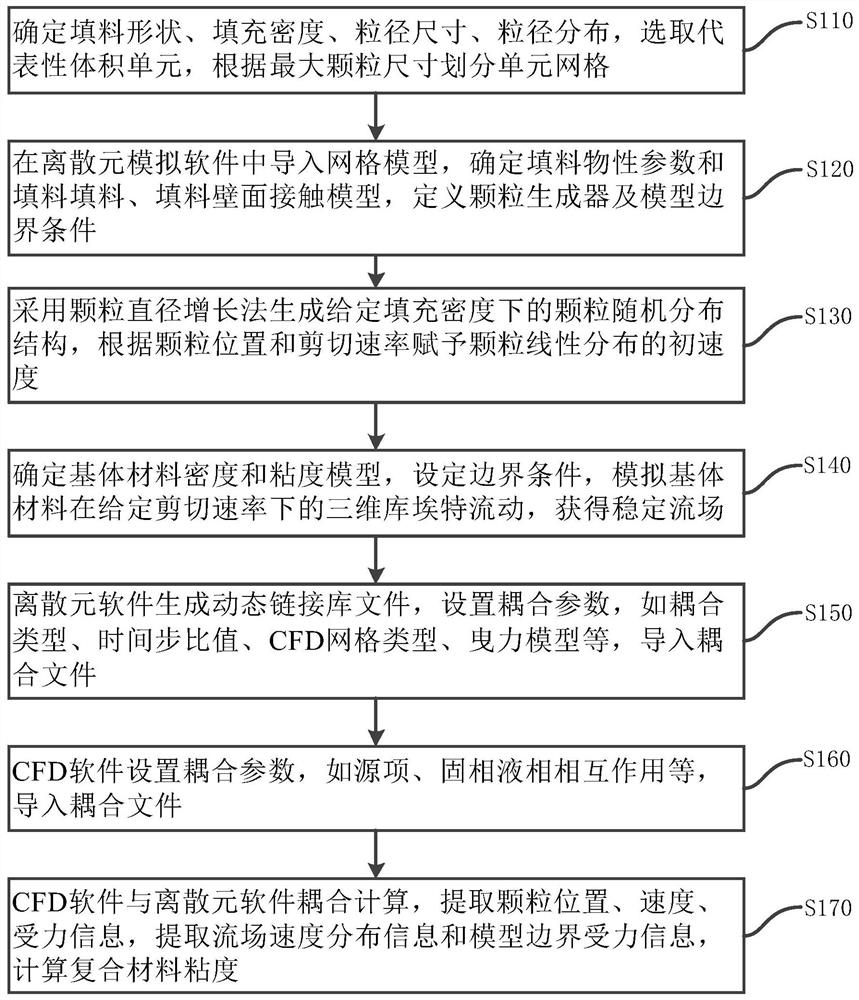
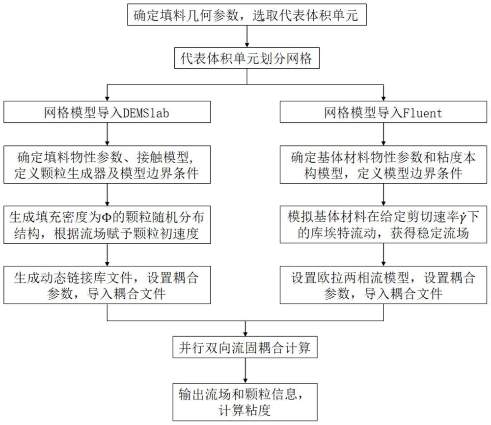
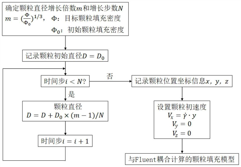
The invention discloses a multi-particle-size filler filling type composite material fluidity simulation method. The method comprises the following steps: setting geometric information of a filler, and dividing unit grids according to the maximum filler particle size; according to discrete element simulation, filler physical property parameters and filler-filler and filler-wall surface contact models are determined, and a particle generator and model boundary conditions are defined; generating a particle random distribution structure by adopting a particle diameter increasing method, and setting an initial velocity of particle linear distribution; determining density and viscosity models of the base material, setting boundary conditions, and simulating three-dimensional Couette flow of the base material at a given shear rate; generating a dynamic link library file by discrete element software, and importing a coupling file; adopting computational fluid mechanics software to set coupling parameters, and importing a coupling file; and calculating the viscosity of the composite material by combining the coupling calculation of computational fluid mechanics software and discrete element software. The method can more accurately and comprehensively analyze the viscosity change rule of various composite materials filled with fillers in different shapes.

Description

technical field [0001] The invention relates to the technical field of polymer composite material design, and more specifically, to a method for simulating the fluidity of a multi-particle size filler-filled composite material. Background technique [0002] Multi-size filler-filled composite materials are widely used in the field of electronic packaging, such as underfill (Underfill), thermal interface material (TIM), etc. As the filling density of fillers increases, agglomeration between fillers tends to occur, the friction effect between fillers increases, and the interface area between fillers and matrix increases, resulting in poor fluidity of composite materials, which is not conducive to material processing and molding. The microscopic factors that affect the macroscopic viscosity of composite materials include: filler packing density, filler particle size, particle size distribution, filler and matrix material properties, etc. It is difficult to analyze the specific ...

Claims


Application Information

Patent Timeline
Patent Type & Authority Applications(China)
IPC IPC(8): G06F30/28G06F30/25G06F113/08G06F113/26G06F119/14
CPCG06F30/28G06F30/25G06F2113/08G06F2113/26G06F2119/14
Inventor 付雪琼鲁济豹孙蓉
Owner SHENZHEN INST OF ADVANCED TECH CHINESE ACAD OF SCI
Learn More