Eureka AIR delivers breakthrough ideas for toughest innovation challenges, trusted by R&D personnel around the world.

Campus security monitoring device

A security monitoring and campus technology, applied to TV, color TV, supporting machines, etc., can solve problems such as troublesome installation methods, large safety hazards, and reduced self-stability, so as to simplify adjustment steps, ensure safety, and reduce occupied space Effect

Pending Publication Date: 2022-04-15
武汉北大营电子工程技术有限公司
View PDF0 Cites 0 Cited by
  • Summary
  • Abstract
  • Description
  • Claims
  • Application Information

AI Technical Summary

Problems solved by technology

[0003] However, the current gun-shaped cameras mainly have the following problems during use: first, when adding a gun-shaped camera to the monitoring pole, it is necessary to manually climb the ladder to a certain height, and then use a screwdriver to install the gun-shaped camera on the monitoring pole. The method is cumbersome, and workers stay at high places for a long time, which poses a great safety hazard; secondly, after the gun camera is installed, it needs to be adjusted manually to ensure that the gun camera can monitor the specified position. The existing adjustment method is generally supported by the worker. The camera uses a screwdriver to lock the adjustment part in one hand. During the operation, the workers hang their hands in the air, which reduces their own stability and is prone to safety accidents. The gun camera used outdoors will have water on the glass cover of the camera when it encounters rain. bead, causing the gun camera to monitor the screen blurred, thereby affecting the normal use of the gun camera

Method used


Image

  • Campus security monitoring device
  • Campus security monitoring device
  • Campus security monitoring device

Examples


Embodiment Construction

[0033] Embodiments of the present invention will be described below with reference to the drawings. In the process, in order to ensure the clarity and convenience of illustration, we may exaggerate the width of the lines or the size of the constituent elements in the diagram.

[0034] In addition, the following terms are defined based on the functions in the present invention, and may be different according to the user's or operator's intention or practice. Therefore, these terms are defined based on the entire content of this specification.

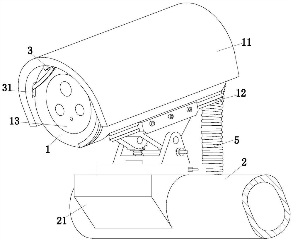
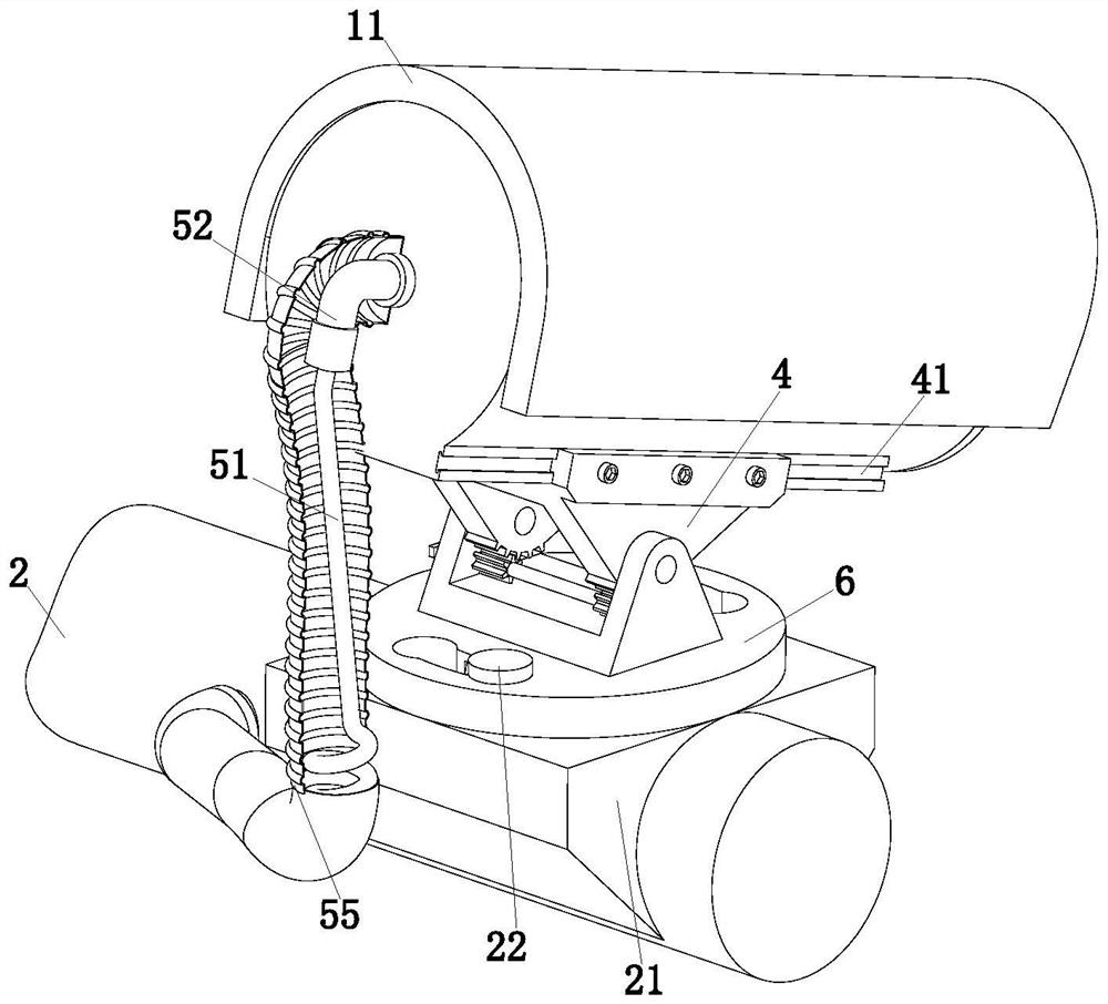
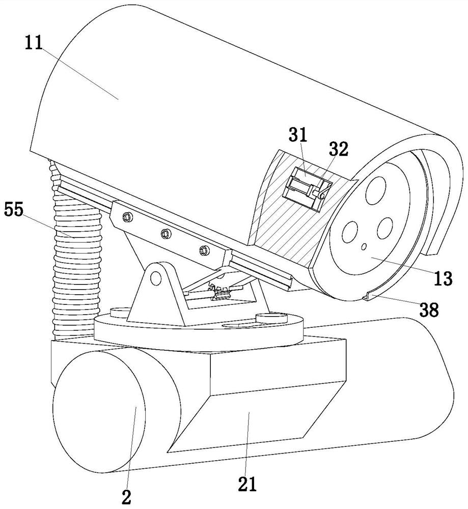
[0035] refer to figure 1 and figure 2 , a campus security monitoring device, including a camera 1, a monitoring rod 2, a clearing device 3, an angle adjustment device 4, a cable auxiliary part 5 and a rotating deck 6; a base 21 is welded on the monitoring rod 2, and the base The upper end surface of the seat 21 is symmetrically provided with a T-shaped column 22, and the rotating deck 6 and the T-shaped column 22 are installed on the...


PUM


Abstract

The invention relates to the technical field of monitoring devices, in particular to a campus security monitoring device. Comprising a camera, a monitoring rod, a removing device, an angle adjusting device, a cable auxiliary part and a rotary clamping seat. The invention solves the following main problems in the use process of the existing gun-shaped camera: firstly, when the gun-shaped camera is added on a monitoring rod, the gun-shaped camera needs to be manually installed by using a screwdriver at a high position, the installation is troublesome, the installation time is long, and the potential safety hazard is large, secondly, the gun-shaped camera needs to be manually adjusted in angle, and the cost is high. According to an existing adjusting mode, a worker holds a camera with one hand and locks the camera with the other hand through a screwdriver, in the operation process, the stability of the worker is reduced, safety accidents are prone to occurring, water drops stay on a glass cover of the camera on rainy days again, monitoring pictures are fuzzy, and normal use of the camera is affected. According to the invention, the installation rate of the gun-shaped camera is improved, the operation steps are simplified, and the monitoring effect is ensured.

Description

technical field [0001] The invention relates to the technical field of monitoring devices, in particular to a campus security monitoring device. Background technique [0002] Campus security often uses various hardware facilities such as video surveillance systems, burglar alarms, and access control systems to ensure campus security. Among them, video surveillance systems often use spherical cameras and gun-shaped cameras; spherical cameras are mostly used indoors, and gun-shaped cameras It is mostly used for outdoor use, and the gun camera used outdoors is usually fixed and installed with a monitoring pole. [0003] However, the current gun-shaped cameras mainly have the following problems during use: first, when adding a gun-shaped camera to the monitoring pole, it is necessary to manually climb the ladder to a certain height, and then use a screwdriver to install the gun-shaped camera on the monitoring pole. The method is cumbersome, and workers stay at high places for a...

Claims


Application Information

Patent Timeline
IPC IPC(8): H04N5/225B08B1/00F16M11/04F16M11/10
CPCY02E10/50
Inventor 杨德林向锐
Owner 武汉北大营电子工程技术有限公司
Why Eureka
Eureka Blog
Learn More